- Designed for unconditionally stable performance in professional communications systems
- Featuring rugged construction
DESIGNED FOR MAXIMUM PERFORMANCE AND EFFICIENCY
Our filters have been selected by some of the leading Public Safety organizations across North America to ensure Mission-Critical performance for their RF networks. Comprod manufactures each cavity filter in North America – skilled RF technicians, quality calibration, and insistence on high-quality plating materials. This ensures that the filter performance will be optimal, tuning can be easily performed by your technicians, and the RF signals remain as pure and clean as possible. Our customers notice the difference in quality and reliability.
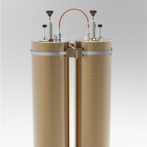
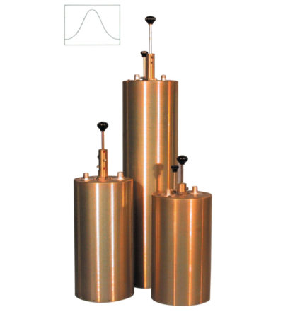
• Four versions of filters available: Band-Pass, Notch, Pass-Reject, and X-Pass, available in 2″, 4″, 6.625″ and 10″ cavities
• 6.625” and 10” filters have two hand-movable tuning rods for faster tuning. Silver-plated adjustable coupling loops and a calibration index label help to facilitate setting the cavity insertion loss as required for each application.
• Combination of a heavy-gauge aluminum outer conductor, thick heliarc-welded cavity top plates, heavy silver-plating on micro-finished tuning assemblies, and Invar-based temperature compensation material for constant performance levels and long-term reliability
• Silver-plated brass bodies, gold- plated center contacts and thru-line cable assemblies that are made with high-quality connectors and RG-393B/U Teflon or RG-214/U cable to provide excellent intermodulation rejection at high system power levels
• Gold-plated cable connector center contacts are soldered to the cable and the dual shield is securely crimped to the connector barrel using pneumatic fixtures and precision dies
-
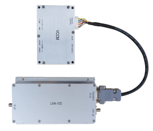
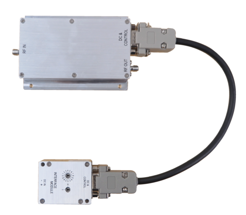
 Models: 58-10-32-ATT (100-225 MHz) These amplifiers will provide higher system dynamic range for fixed receiver systems, tower mounted amplifiers, or boosters.
 -
Model: 58-10-32-ATT-DC (100-225 MHz) In case of failure (DC off or out of range), the RF signal is bypassed, dry contact and red LED alarm are activated.
- Designed for unconditionally stable performance in professional communications systems
- Featuring rugged construction
-
Models: 58-30-32-ATT (380-520 MHz) These amplifiers will provide higher system dynamic range for fixed receiver systems, tower mounted amplifiers, or boosters.
- Designed for unconditionally stable performance in professional communications systems
- Featuring rugged construction
-
Model: 58-30-32-ATT-DC (380-520 MHz) In case of failure (DC off or out of range), the RF signal is bypassed, dry contact and red LED alarm are activated.
- Designed for unconditionally stable performance in professional communications systems
- Featuring rugged construction
-
Models: 58-70-32-ATT (700-1000 MHz) These amplifiers will provide higher system dynamic range for fixed receiver systems, tower mounted amplifiers, or boosters.
- Designed for unconditionally stable performance in professional communications systems
- Featuring rugged construction
-
Model: 58-70-32-ATT-DC (700-1000 MHz) In case of failure (DC off or out of range), the RF signal is bypassed, dry contact and red LED alarm are activated.
- Designed for unconditionally stable performance in professional communications systems
- Featuring rugged construction
-
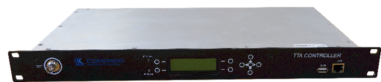
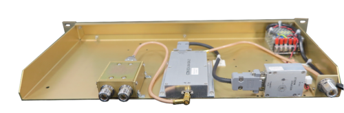
Top-Tower Amplifier Our modular Tower-Top Amplifier (TTA) systems provide superior receiver system performance and excellent electrical reliability by improving base station Up Link (UL) sensitivity. TTA systems overcome link budget imbalance between the Up Link and Down Link (DL) by boosting received signal to overcome received path loss (feeder losses).
- Improved base station UL sensitivity
- Redundant LNA with automatic change over
- LNA bypass modes
- Monitoring & Control via GUI
- SNMP Alarms
- Remote Access
-
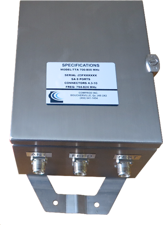
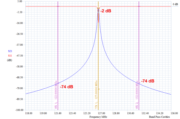
Designed to minimize interference from adjacent channels and outside systems
- Available in single, dual or triple units
- Temperature compensated to ensure frequency stability
- High attenuation
- Adjustable loops: each cavity has a calibration index to reference insertion loss
-
Designed to minimize interference from adjacent channels and outside systems
- Available in single, dual or triple units
- Temperature compensated to ensure frequency stability
- High attenuation
- Adjustable loops: each cavity has a calibration index to reference insertion loss
-
Designed to minimize interference from adjacent channels and outside systems
- Available in single, dual or triple units
- Temperature compensated to ensure frequency stability
- High attenuation
- Adjustable loops: each cavity has a calibration index to reference insertion loss
-
Designed to minimize interference from adjacent channels and outside systems
- Available in single, dual or triple units
- Temperature compensated to ensure frequency stability
- High attenuation
- Adjustable loops: each cavity has a calibration index to reference insertion loss
-
Designed to minimize interference from adjacent channels and outside systems
- Available in single, dual or triple units
- Temperature compensated to ensure frequency stability
- High attenuation
- Adjustable loops: each cavity has a calibration index to reference insertion loss