Description
Top-Tower Amplifier
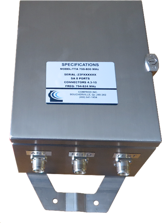
Our modular Tower-Top Amplifier (TTA) systems provide superior receiver system performance and excellent electrical reliability by improving base station Up Link (UL) sensitivity. TTA systems overcome link budget imbalance between the Up Link and Down Link (DL) by boosting received signal to overcome received path loss (feeder losses).
- Improved base station UL sensitivity
- Redundant LNA with automatic change over
- LNA bypass modes
- Monitoring & Control via GUI
- SNMP Alarms
- Remote Access
Our TTA systems include Receiver Multicoupler (RCM) and Tower Top Unit (TTA). They are available in 8 ports and expandable, if needed, to 16 or 32 ports.
The tower top unit is enclosed in a rugged, weather-proof Stainless Steel enclosure with a durable finish to resist rusting and corrosion. The enclosure houses best in class lightning surge protector that protects the ports and prevents failure of the unit from lightning strikes.
Base Station Unit has redundant quadrature coupled low noise amplifiers with a built-in bypass capability that provide greater reliability and better performance. This circuit provides useful gain should only one device be operational. A hermetically sealed, high-reliability bypass relay will fully remove the amplifier from the circuit and provide a non-amplified connection from the antenna to keep the system up and running even if the preamplifier totally ceases operation. Bypass modes are activated when DC power to the tower unit is disabled, or damage occurs to the LNA.
The tower housing has two drain holes to release any water due to condensation build up. RF connections stay weather-resistant longer as a result of the protection provided by a 360° drip-edge.
Superior electrical performance starts with a highly selective filter that provides excellent out-of-band rejection with minimum loss. Our preamplifier provides low noise performance (NF=1.8 dB typical) and high intermodulation immunity (TOI=16.9 dB for 10 dB system gain) across standard operating gain levels.

