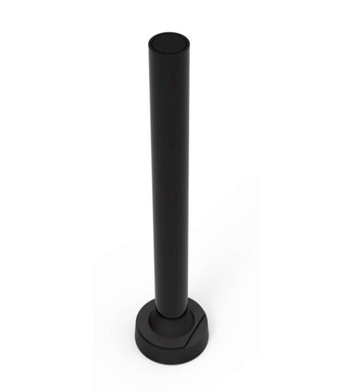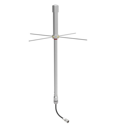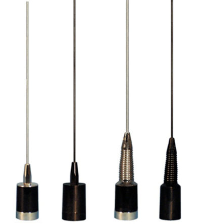
- 3.0 dBd gain achieved by featuring a 5/8-wave whip with a base loaded matching coil
- Manufactured using the best corrosion-resistant materials and finishes available
- Triple-plated chrome brass with a large insert molded low-loss coil form and spring-loaded, gold-plated contact
- Large diameter coil form which allows for a wider operational bandwidth and better matching characteristics
- Rubber boot and overlap construction to ensure a moisture-proof installation
- Standard Motorola NMO type mount
-

-
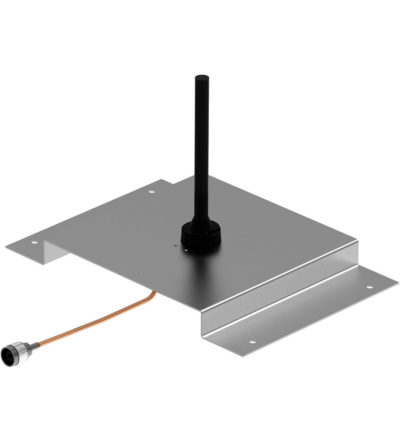
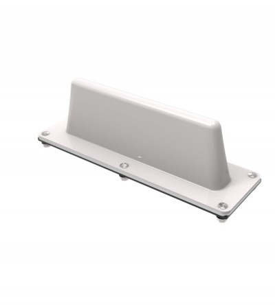
Ideal for low clearance applications such as those found on trains, public transit vehicles, construction equipment and police vehicles
- Low-profile rugged alternative to a ¼-wave whip mobile antenna
- When mounted on a horizontal surface, maximum radiation is omnidirectional and vertically polarized
- High strength cast aluminum design. Can be coated for additional protection against harsh environmental conditions
- Supplied with an O-ring to ensure a moisture-proof installation
-
Individually calibrated to ensure the best performance in a disguised appearance
- Two or three separate frequency segments in a given mobile band
- Cross-channel operation in two mobile bands with one antenna
- Alternative antennas to an OEM version will be recommended, where required (e.g. Euro-style, or universal mount traditional whip)
-
Combines multiple receiver frequencies onto the same antenna
- A low noise amplifier provides gain across the frequency band
- Low noise figure and low intermodulation generation
- Features up to 16 ports (24 and 32 port versions are available)
- -30 dB signal sampler port that can also be used to inject a signal
-
Designed for external Public Safety Radio Frequencies to propagate within buildings, tunnels or public use environments
- Multiple frequency bands
- Aluminum painted
-
Designed for external Public Safety Radio Frequencies to propagate within buildings, tunnels or public use environments
- Aluminium painted
-
Ideal for low clearance applications such as those found on trains, public transit vehicles, construction equipment and police vehicles
- Low-profile rugged alternative to a ¼-wave whip mobile antenna
- When mounted on a horizontal surface, maximum radiation is omnidirectional and vertically polarized
- Impact-resistant ABS radome
- Supplied with a mounting gasket to ensure a moisture-proof installation
-
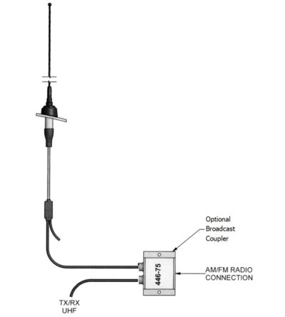
Very large bandwidth which make it ideal for emergency use or resale
- Available in UHF configuration (3 frequency splits)
- Rugged design to withstand the most extreme environmental conditions
- The mounting hardware supplied will permit 0.75” to 2.3/8” O.D. pipe installation.
- DC ground for lightning protection
-
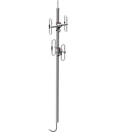
DOWNLOAD PDF DOWNLOAD DIGITAL PATTERNSIdeal for applications where costs are calculated per antenna
- Available in many configurations
- VHF, UHF or 700/800/900 MHz antennas can be combined onto one mast
- Mix and match with our 770, 790, 840, 870 and 880 series antennas
- Can be configured for side or top mount
- Low VSWR version with maximum gain over specified frequency
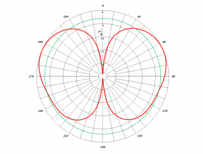
- Certain versions of antennas have an adjustable pattern for 3 dBd omnidirectional or 6 dBd offset coverage
- Heavy-duty versions available
-
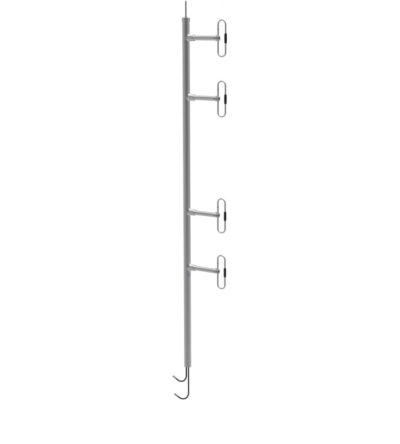
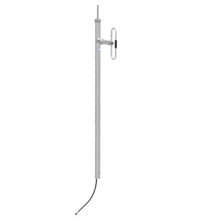
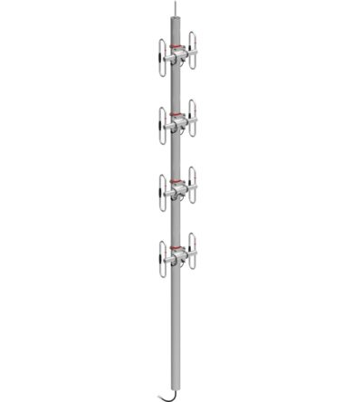
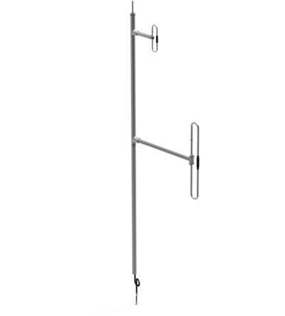
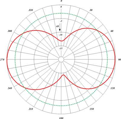
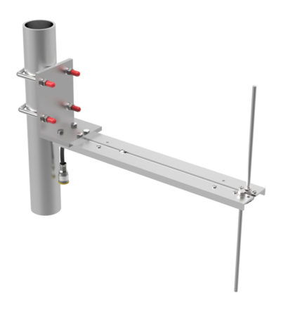
Adjustable or fixed, side mount or top mount antenna
- Available in 1, 2, 4, 8 and dual dipole configurations
- Offered in a 1/4, 3/8, or 1/2 wave versions
- Internal cabling and fixed dipole-mast spacing
- Heavy-duty and black anodized versions available
-
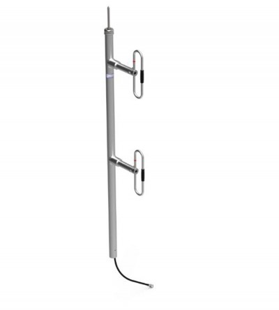
Adjustable or fixed, side mount or top mount antenna
- Available in 1, 2, 4, 8 and dual dipole configurations
- Offered in a 1/4, 3/8, or 1/2 wave versions
- Internal cabling and fixed dipole-mast spacing
- Heavy-duty and black anodized versions available
-
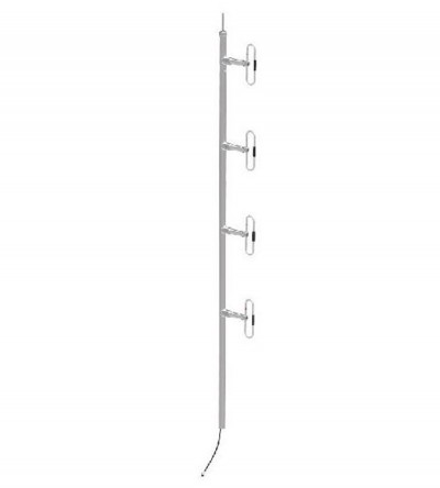
Adjustable or fixed, side mount or top mount antenna
- Available in 1, 2, 4, 8 and dual dipole configurations
- Offered in a 1/4, 3/8, or 1/2 wave versions
- Internal cabling and fixed dipole-mast spacing
- Heavy-duty and black anodized versions available
-
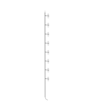
Adjustable or fixed, side mount or top mount antenna
- Available in 1, 2, 4, 8 and dual dipole configurations
- Offered in a 1/4, 3/8, or 1/2 wave versions
- Internal cabling and fixed dipole-mast spacing
- Heavy-duty and black anodized versions available
-
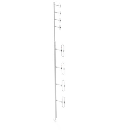
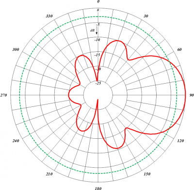
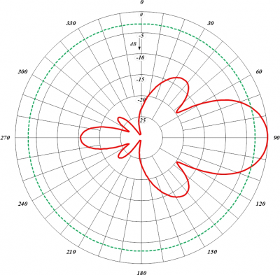
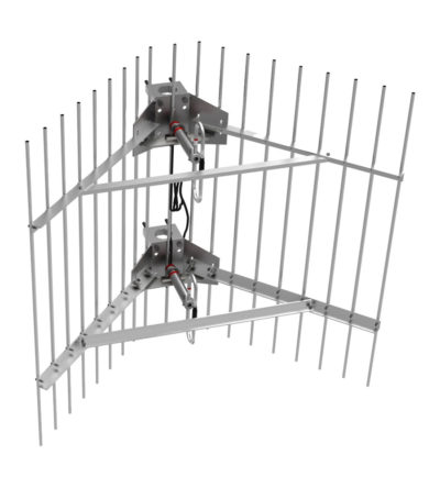
DOWNLOAD PDF DOWNLOAD DIGITAL PATTERNSOffered in Omni or bi-directional versions
- Available in 2 and 4 dipole set configurations
- Complete internal cabling, fixed dipole-mast spacing, and adjustable pattern control
- Heavy-duty, black anodized and top mount configuration only versions available
-
Offered in Omni or bi-directional versions
- Available in 2 and 4 dipole set configurations
- Complete internal cabling, fixed dipole-mast spacing, and adjustable pattern control
- Heavy-duty, black anodized and top mount configuration only versions available
-
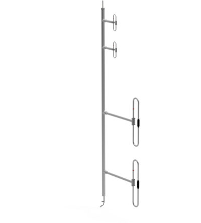
Ideal for applications where costs are calculated per antenna
- Available in many configurations
- VHF, UHF or 700/800/900 MHz antennas can be combined onto one mast
- Mix and match with our 770, 790 and 870 series antennas
- Can be configured for side or top mount
- Low VSWR version with maximum gain over the specified frequencies
- Heavy-duty versions available
-
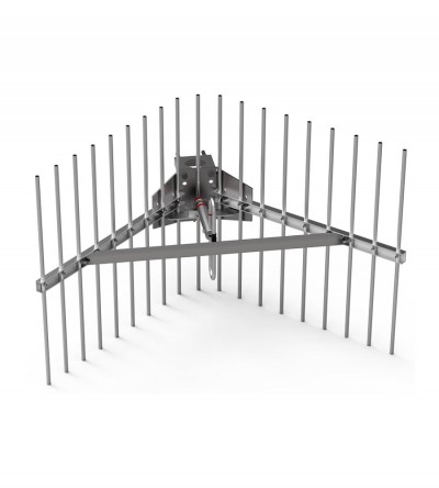
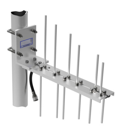
Rugged design to withstand harsh environmental conditions
- Available in 2, 3, 7 element and 70 MHz wideband configurations
- Vertical or horizontal polarization
- DC ground for lightning protection
- Fully welded for added durability
- Black anodized and heavy-duty versions available
-
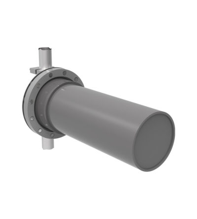
DOWNLOAD PDF DOWNLOAD DIGITAL PATTERNHeavy-duty versions, part of our “Avalanche Series
- Rugged design to withstand harsh environmental conditions
- Available in UHF configuration (3 frequency splits)
- Vertical or horizontal polarization
- DC ground for lightning protection
- The PVC enclosure is ½ inch-thick water main.
-
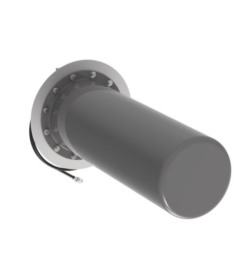
Heavy-duty versions, part of our “Avalanche Series
- Rugged design to withstand harsh environmental conditions
- Available in UHF configuration (3 frequency splits)
- Vertical or horizontal polarization
- DC ground for lightning protection
-
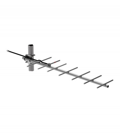
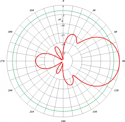
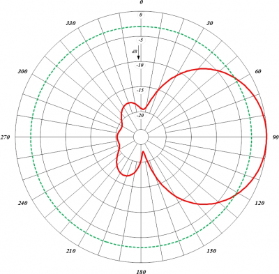
Broadband, ideal for point-to-point applications
- Available in VHF, UHF, 700/800/900 MHz configurations
- Good directivity, very high front-to-back ratio
- Performance is constant throughout the band
- Rugged design to withstand harsh environmental conditions
- Ultra-low VSWR ratings
- Vertical or horizontal polarization
- DC ground for lightning protection
- Heavy-duty versions available
-
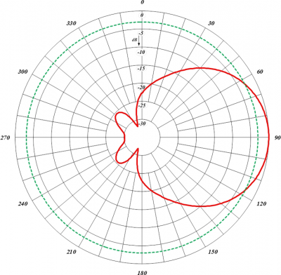
DOWNLOAD PDF DOWNLOAD DIGITAL PATTERNWide band, ideal for base station or in-building applications
- Available in UHF configuration (3 frequency splits)
- Very high front-to-back ratio
- Performance is constant throughout the band
- Rugged design to withstand harsh environmental conditions
- Vertical or horizontal polarization
- DC ground for lightning protection
-
Wide band, ideal for base station or in-building applications
- Very high front-to-back ratio
- Performance is constant throughout the band
- Rugged design to withstand harsh environmental conditions
- Vertical or horizontal polarization
- DC ground for lightning protection
-
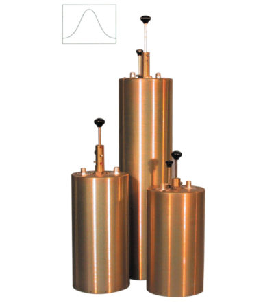
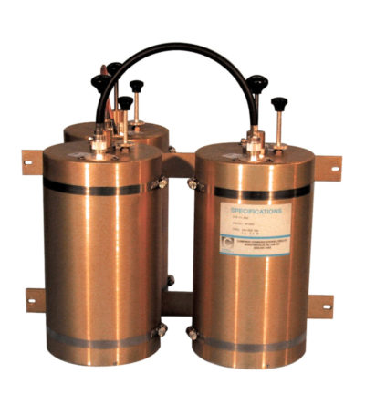
Designed to minimize interference from adjacent channels and outside systems
- Available in single, dual or triple units
- Temperature compensated to ensure frequency stability
- High attenuation
- Adjustable loops: each cavity has a calibration index to reference insertion loss
-
Designed to pass a frequency band and reject a narrow band of frequencies
- Can reject frequencies on either the high or low side of the pass frequency
- Temperature compensated to ensure frequency stability
- High attenuation to minimize desense and interference
-
Designed to reject one narrow band of frequencies, while letting all others pass in the operating band
- Can be cascaded or added to one another in order to sharpen the attenuation of the rejection curve
- Temperature compensated to ensure frequency stability
- High attenuation to minimize desense and interference from adjacent systems
- Adjustable loops: each cavity has a calibration index
-
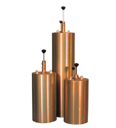
Designed for minimizing interference from adjacent channels and outside systems
- Available in single, dual, triple or additional units
- Temperature compensated to ensure frequency stability
- High attenuation to minimize desense and interference from adjacent systems
- Adjustable loops: each cavity has a calibration index for easy field tuning
-
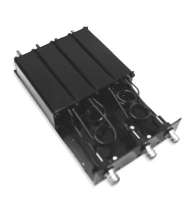
Features compact size, low loss and temperature compensation over the range of -40ºC to +60ºC
- Extruded aluminum cavities and solid- shield copper-jacketed inter-cabling that ensures excellent mechanical and electrical stability
- All units are adjustable in the field and rated at 50 Watts maximum with a maximum VSWR of 1.5: 1 over the entire tuning range.
- BNC connectors are standard.
-
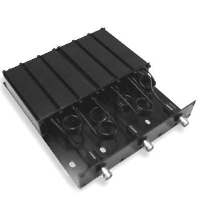
Features compact size, low loss and temperature compensation over the range of -40ºC to +60ºC
- Extruded aluminum cavities and solid- shield copper-jacketed inter-cabling that ensures excellent mechanical and electrical stability
- All units are adjustable in the field and rated at 50 watts continuous duty with a maximum VSWR of 1.5: 1 over the entire tuning range.
- BNC connectors are standard.
-
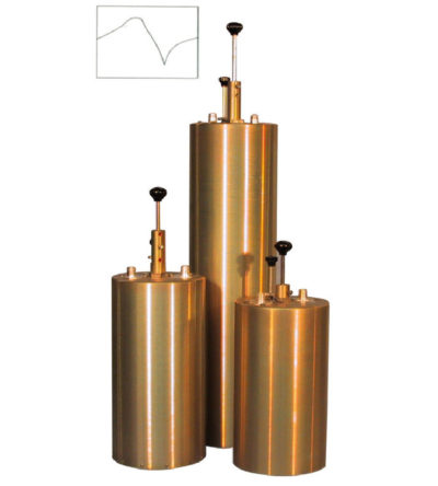
Designed for flexible, close frequency systems
- Each cavity has both a Reject and a Pass band curve
- Available in single units, they can be combined with band pass, notch, and pass reject cavities for added protection and isolation
- Temperature compensated to ensure frequency stability
- High attenuation to minimize desense and interference from adjacent systems
- Adjustable loops: each cavity has a calibration index for easy field tuning
-
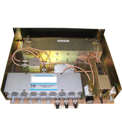
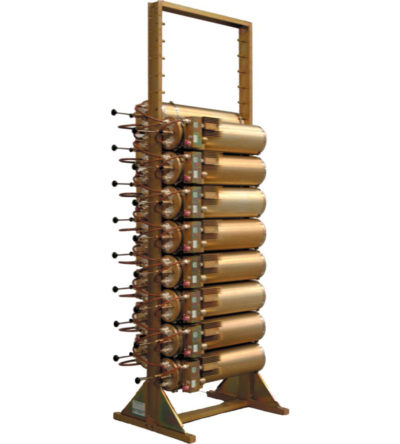
Incorporates expandability, close frequency spacing and some of the lowest insertion losses in the industry
- Can easily support 125 kHz Tx-Tx spacing or 75 kHz spacing while using 10” cavities
- Flexible design: from 1-21 channel capacity
- Expandable: 1 or more additional channels at a time; re-configurable equipment
- 380-512 MHz, 132 MHz of operating bandwidth
- Temperature compensation to ensure frequency stability
- High attenuation to minimize desense and interference
- Ultra-low insertion losses; low coupling and bridging losses
- Continuous high-power handling capability; 150 watts – 24/7