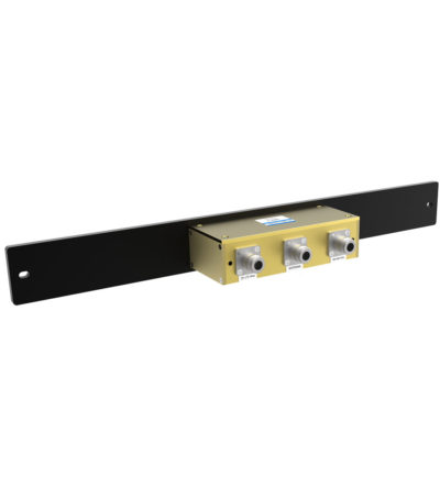
- Allows multiple bands to share the same transmission lines
- Available in VHF, UHF and 800/900 MHz bands
- Can be Tower-Mounted (TM), Rack-Mounted (RM) or stand alone
-
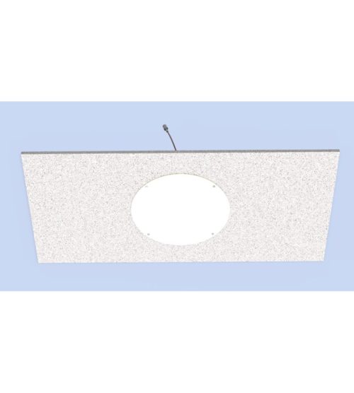
 Designed for easy installation, reducing coaxial runs, and in-building applications with multi-band antennas
 -
Usage for Distributed Antenna Systems (DAS) for Public Safety or LTE communication in multiple stories of a building.
- Mounting on a ceiling or gyprock wall, without need of a ground plane
-
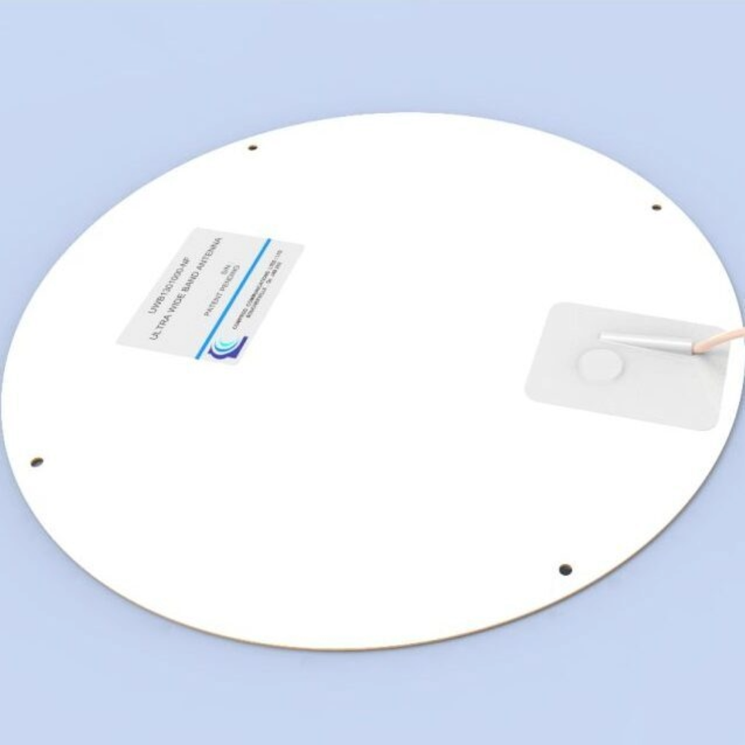
Usage for Distributed Antenna Systems (DAS) for Public Safety or LTE communication in multiple stories of a building. The antenna’s main application includes usage for:
- Distributed Antenna Systems (DAS) for Public Safety
- LTE communication
- Cellular bands in multiple stories of a building
- Mounting on a ceiling or gyprock wall, without need of a ground plane
-
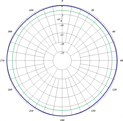
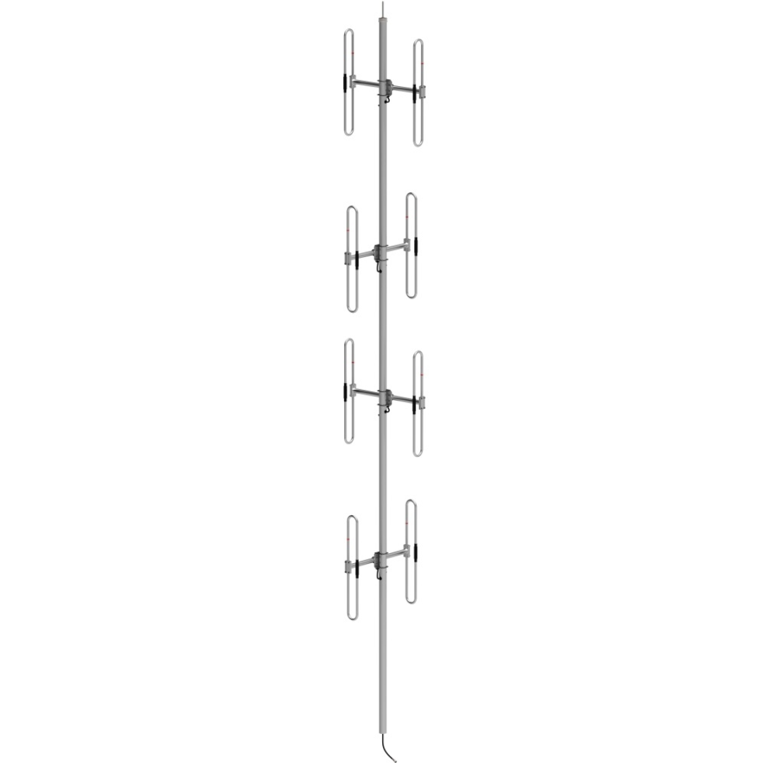
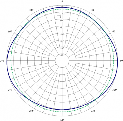
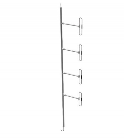
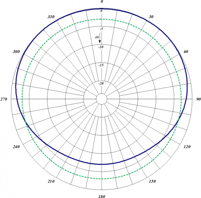
880 Aviation Series. Offered in omnidirectional or bi-directional versions
- Internal cabling, fixed dipole-mast spacing and adjustable pattern control
- Heavy-duty, black anodized versions available
-
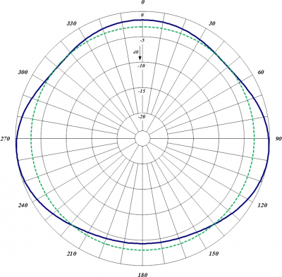
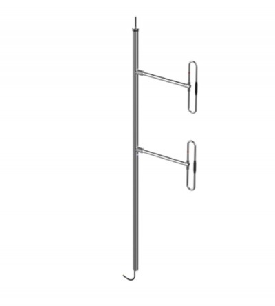
880 Aviation Series. Offered in omnidirectional or bi-directional versions
- Internal cabling, fixed dipole-mast spacing and adjustable pattern control
- Heavy-duty, black anodized versions available
-
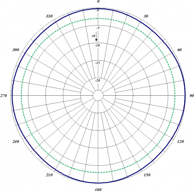
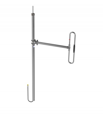
870 Aviation Series. Adjustable, fixed, side or top mount antenna
- Offered in a 1/4 or 3/8 wave spacing version
- The 874A-70-A has external cabling and a field-adjustable pattern.
- The 874F-70-A has internal cabling and fixed dipole-mast spacing.
- Heavy-duty and black anodized versions available
-
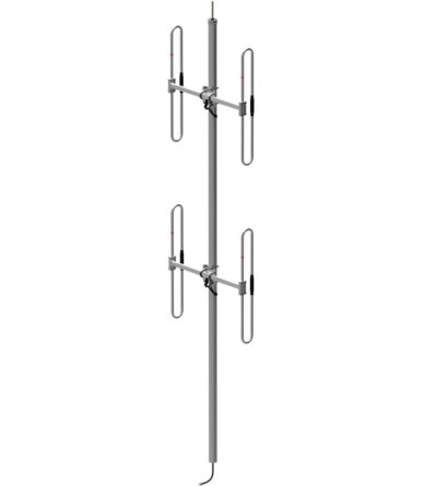
870 Aviation Series. Adjustable, fixed, side or top mount antenna
- Offered in a 1/4 or 3/8 wave spacing version
- The 872A-70-A has external cabling and a field-adjustable pattern.
- The 872F-70-A has internal cabling and fixed dipole-mast spacing.
- Heavy-duty and black anodized versions available
-
870 Aviation Series. Adjustable, fixed, side or top mount antenna
- Offered in a 1/4 or 3/8 wave spacing version
- The 871A-70-A has external cabling and a field-adjustable pattern.
- The 871F-70-A has internal cabling and fixed dipole-mast spacing.
- Heavy-duty and black anodized versions available
-
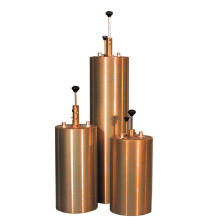
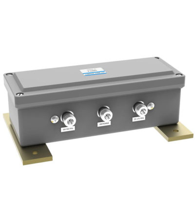
Designed for flexible, close frequency systems
- Each cavity has both a Reject and a Pass band curve
- Available in single units, they can be combined with band pass, notch, and pass reject cavities for added protection and isolation
- Temperature compensated to ensure frequency stability
- High attenuation to minimize desense and interference from adjacent systems
- Adjustable loops: each cavity has a calibration index for easy field tuning
-
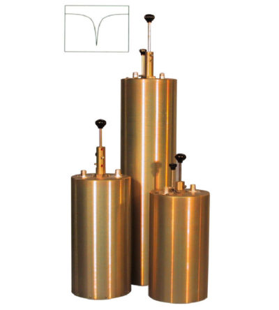
Designed to reject one narrow band of frequencies, while letting all others pass in the operating band
- Can be cascaded or added to one another in order to sharpen the attenuation of the rejection curve
- Temperature compensated to ensure frequency stability
- High attenuation to minimize desense and interference from adjacent systems
- Adjustable loops: each cavity has a calibration index
-
Designed to pass a frequency band and reject a narrow band of frequencies
- Can reject frequencies on either the high or low side of the pass frequency
- Temperature compensated to ensure frequency stability
- High attenuation to minimize desense and interference
-
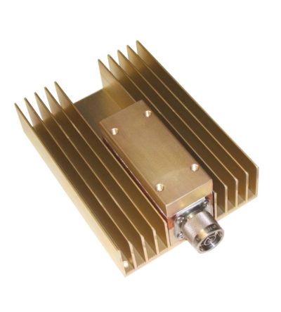
Specifically designed to continually absorb reflected power
- Excellent return loss
- Oversized heat sinks
- Continuous duty power:
- 24/7 operation
- Install-and-forget