- Rugged design to withstand the most extreme environmental conditions
- The mounting hardware supplied will permit 0.75” to 2.3/8” O.D. pipe installation.
- DC ground for lightning protection
-
 Very large bandwidth which make it ideal for emergency use or resale
 -
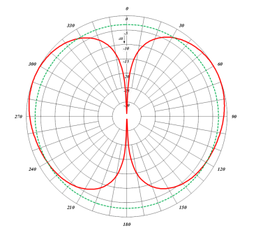
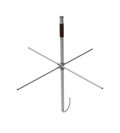
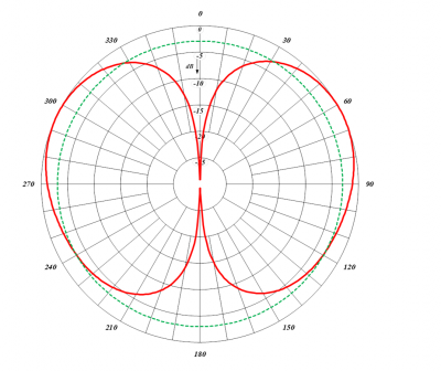
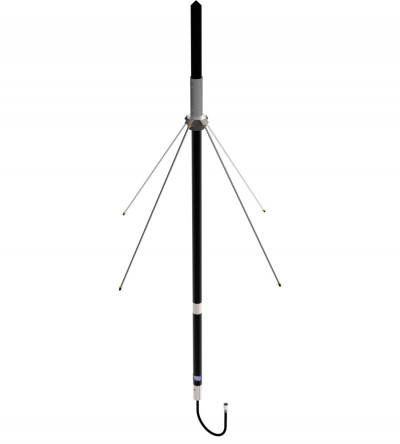
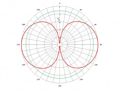
Omnidirectional antenna for wide frequency band applications. Ideal for mounting on buildings
- Available in VHF configuration (3 frequency splits)
- Rugged design to withstand the most extreme environmental conditions.
- The mounting hardware supplied will permit 0.75” to 2.38” O.D. pipe installation.
- DC ground for lightning protection
-
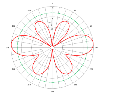
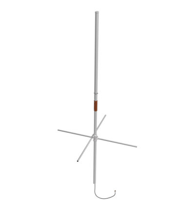
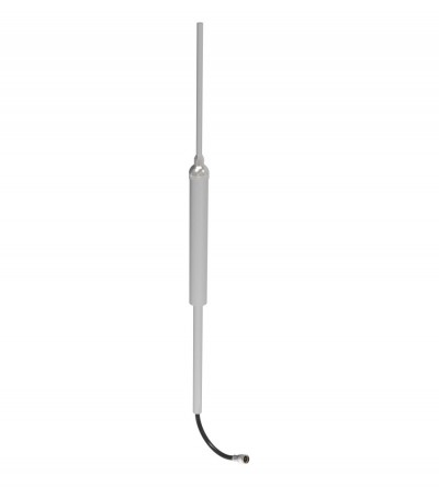
Omnidirectional antenna for wide frequency band applications. Ideal for mounting on buildings
- Available in VHF configuration (2 frequency splits)
- Rugged design to withstand the most extreme environmental conditions.
- The mounting hardware supplied will permit 0.75” to 2.38” O.D. pipe installation.
- DC ground for lightning protection
-
Omnidirectional antenna for wide frequency band applications. Ideal for mounting on buildings
- Available in VHF configuration (1 frequency split)
- Rugged design to withstand the most extreme environmental conditions.
- The mounting hardware supplied will permit 0.75” to 2.38” O.D. pipe installation.
- DC ground for lightning protection
-
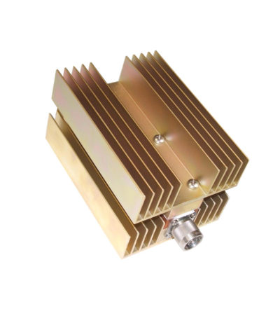
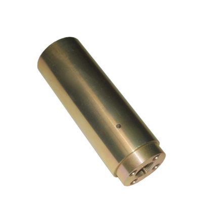
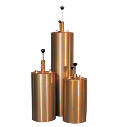
Specifically designed to continually absorb reflected power
- Excellent return loss
- Oversized heat sinks
- Continuous duty power:
- 24/7 operation
- Install-and-forget
-
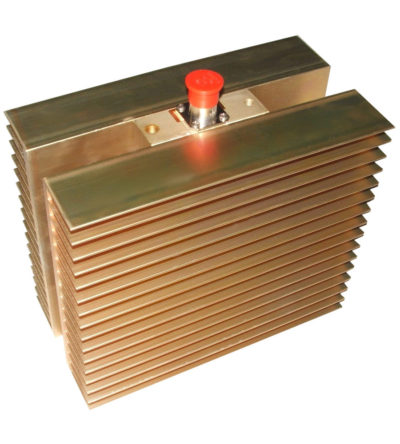
Specifically designed to continually absorb reflected power
- Excellent return loss
- Oversized heat sinks
- Continuous duty power:
- 24/7 operation
- Install-and-forget
-
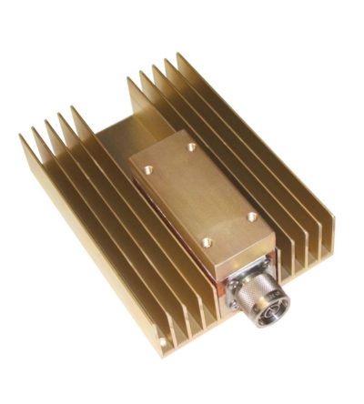
Specifically designed to continually absorb reflected power
- Excellent return loss
- Oversized heat sinks
- Continuous duty power:
- 24/7 operation
- Install-and-forget
-
Specifically designed to continually absorb reflected power
- Excellent return loss
- Oversized heat sinks
- Continuous duty power:
- 24/7 operation
- Install-and-forget
-
Specifically designed to continually absorb reflected power
- Excellent return loss
- Oversized heat sinks
- Continuous duty power:
- 24/7 operation
- Install-and-forget
-
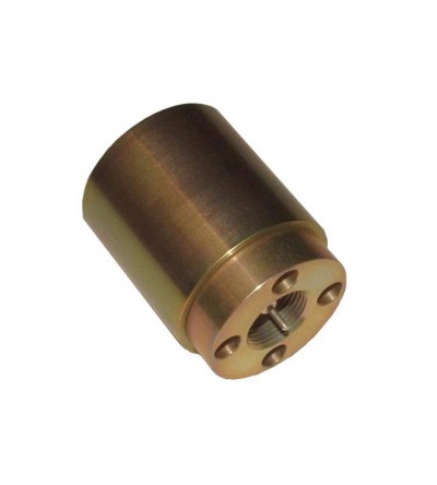
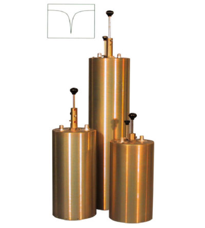
Designed to pass a frequency band and reject a narrow band of frequencies
- Can reject frequencies on either the high or low side of the pass frequency
- Temperature compensated to ensure frequency stability
- High attenuation to minimize desense and interference
-
Designed to reject one narrow band of frequencies, while letting all others pass in the operating band
- Can be cascaded or added to one another in order to sharpen the attenuation of the rejection curve
- Temperature compensated to ensure frequency stability
- High attenuation to minimize desense and interference from adjacent systems
- Adjustable loops: each cavity has a calibration index
-
Designed for flexible, close frequency systems
- Each cavity has both a Reject and a Pass band curve
- Available in single units, they can be combined with band pass, notch, and pass reject cavities for added protection and isolation
- Temperature compensated to ensure frequency stability
- High attenuation to minimize desense and interference from adjacent systems
- Adjustable loops: each cavity has a calibration index for easy field tuning