-
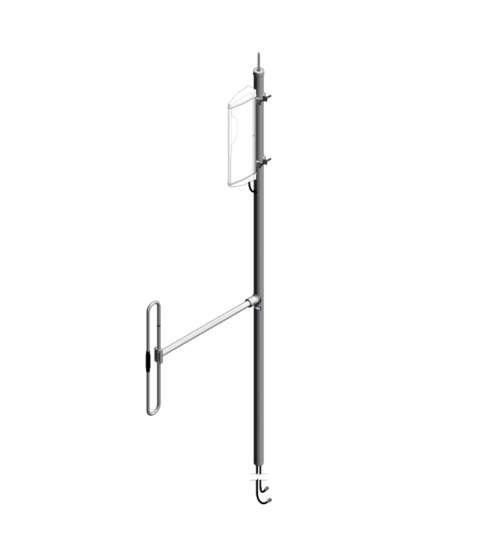
 The F-3980 is a wide band dual antenna with an 871F-70 on the base and a 792-70 on the top. The antenna offers for the 871F-70 a choice of radiation patterns that are determined by the dipole-to-mast spacing. The F-3980 has an internal cabling and is not field adjustable. The 871F-70 antenna is offered in a ¼, 3/8, or ½ wave pattern spacing versions. SPEC Sheet
 -
Ideal for compact high performance applications
- Designed for the combination of two frequencies that require extra isolation. Can also be used as efficient pre-selectors
- An eight cavity configuration is also available for a higher level of isolation and selectivity
- Can be retuned in the field
-
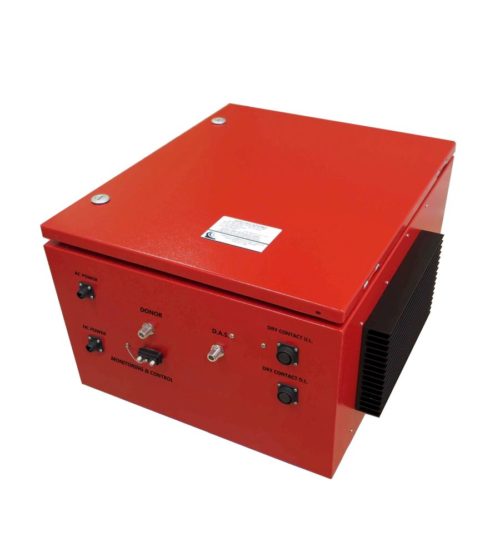
Designed and engineered to meet the fire protection codes (NFPA and IFC standards). Please, note that BDA380512 is a generic number. Actual order number will be assigned to a system design. Specific frequencies are required for this product design.
- Rack mounted or in NEMA 4/4x waterproof, stainless steel enclosures
- Low noise figure, wide dynamic range
- Visual alarms and remote failure monitoring with Graphical User Interface
- FCC and IC certified
- FCC ID: WDM-BDA380512
- IC: 7755A-BDA380512
-
Designed and engineered to meet the fire protection codes (NFPA and IFC standards). Please, note that BDA138174 is a generic number. Actual order number will be assigned to a system design. Specific frequencies are required for this product design.
- Rack mounted or in NEMA 4/4x waterproof, stainless steel enclosures
- Low noise figure, wide dynamic range
- Visual alarms and remote failure monitoring with Graphical User Interface
- FCC and IC certified
- FCC ID: WDM-BDA138174
- IC: 7755A-BDA138174
-
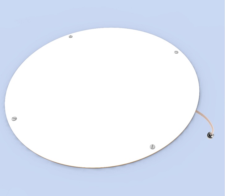
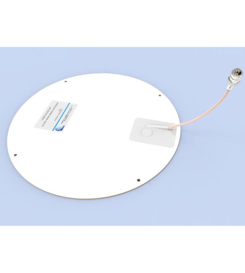
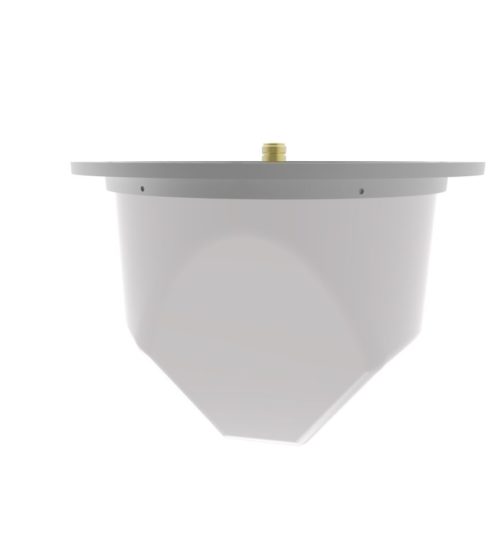
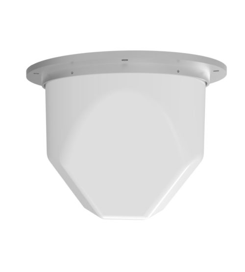
Usage for Distributed Antenna Systems (DAS) for Public Safety or LTE communication in multiple stories of a building.
- Mounting on a ceiling or gyprock wall, without need of a ground plane
- An extra protection can be added to meet the recommended fire safety practices of both the Federal Transit Administration (FTA) and the Federal Rail Administration (FRA) for smoke emission and flammability as tested under ASTM E-662 and ASTM E-162
-
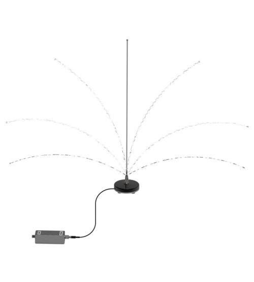
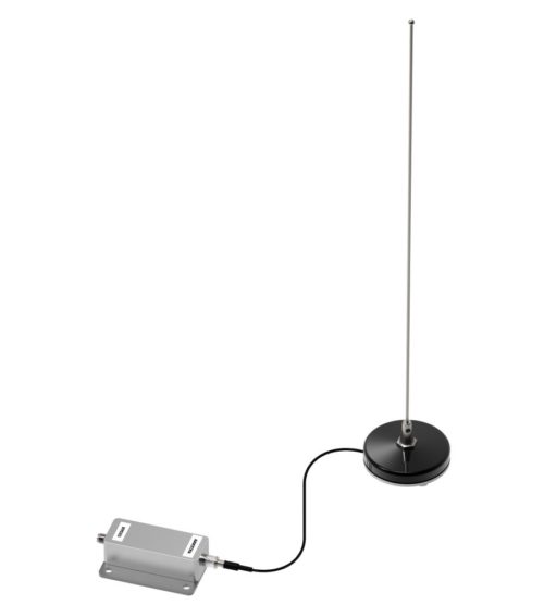
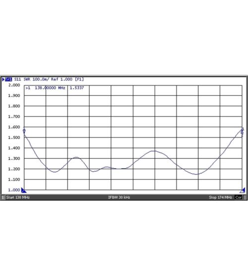
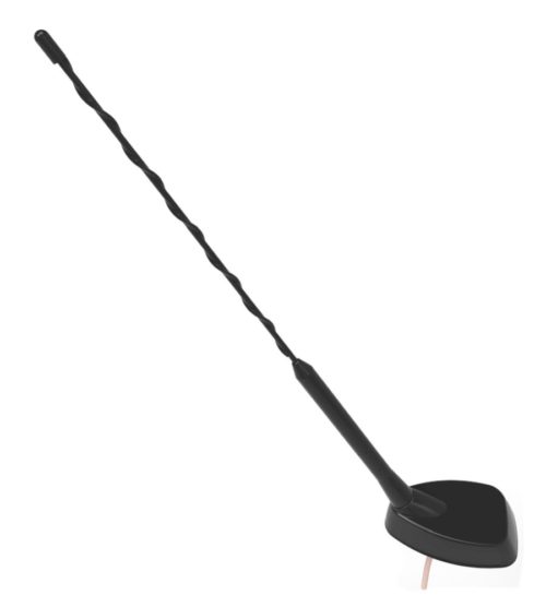
- Frequency range of 138-174 MHz
- Unity gain achieved over its operating bandwidth
- Used for vehicles, such as ambulances, where vertical clearance is critical
- This antenna is ideal for a vehicle that enters areas with reduced headroom
- Combined with a matching circuit that is mounted inside the vehicle
- Each antenna assembly is individually calibrated on the roof of a vehicle
-
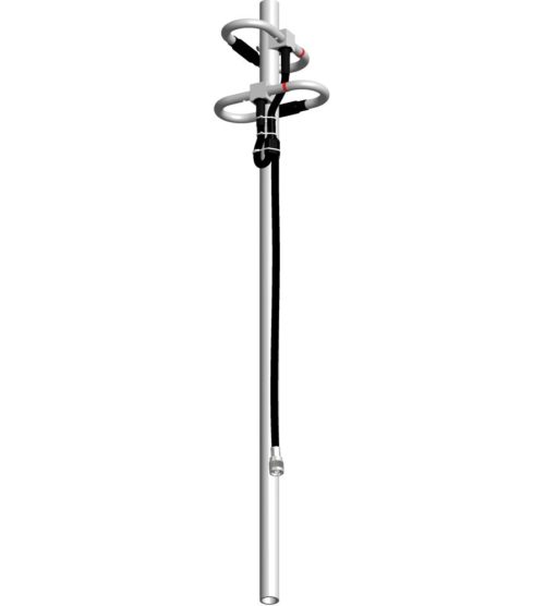
Constructed from high strength, corrosion resistant aluminum alloy and stainless steel
- Available in VHF, UHF, 800/900 MHz configurations
- Rugged design to withstand harsh environmental conditions
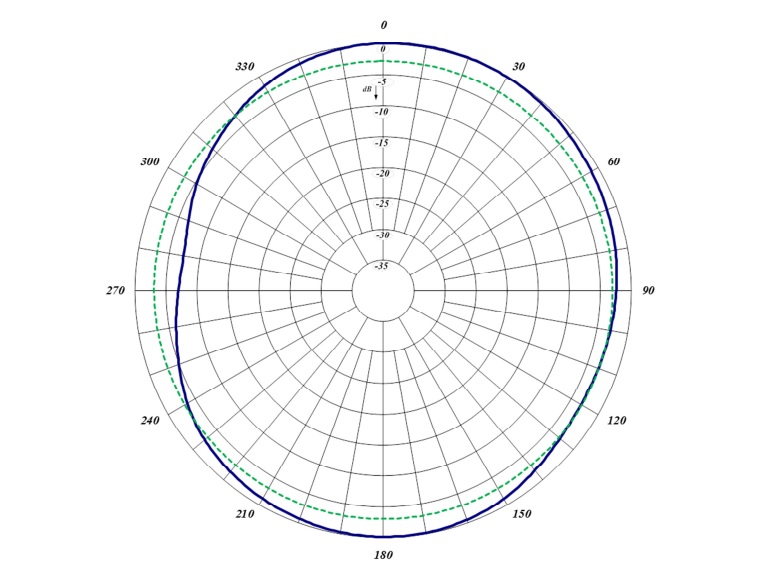
- Circular polarization
- DC ground for lightning protection
-
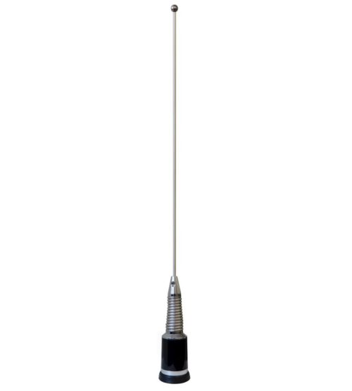
- Gain of unity over its operating bandwidth
- Manufactured using the best corrosion-resistant materials and finishes available
- Triple-plated chrome brass with a large insert molded low-loss coil form and spring-loaded, gold-plated contact
- Rubber boot to ensure a moisture-proof installation
- Standard TAD / NMO type mount
-
Designed for quick and easy installations
- Designed for the combination of two frequencies requiring extra isolation. Can also be used as efficient pre-selectors
- Available in 4 or 6 cavity configurations
- Temperature compensated to ensure frequency stability
- High attenuation to minimize desense and interference from adjacent systems
- Adjustable loops: each cavity has a calibration index for easy field tuning
-
Individually calibrated to ensure the best performance in a disguised appearance
- Two or three separate frequency segments in a given mobile band
- Cross-channel operation in two mobile bands with one antenna
- Alternative antennas will be recommended, where required (e.g. Euro-style, or universal mount traditional whip)
-
Designed for external Public Safety Radio Frequencies to propagate within buildings, tunnels or public use environments
- Offered with Fire Retardant 6200 Kydex
- Meets the recommended fire safety practices of both the Federal Transit Administration (FTA) and the Federal Rail Administration (FRA) for smoke emission and flammability as tested under ASTM E-662 and ASTM E-162
- The F-3749B Antenna is available in custom colors for orders of 150 or more.
-
Ideal for compact high performance applications
- Designed for the combination of two frequencies that require extra isolation. Can also be used as efficient pre-selectors
- A six and an eight cavity configuration is also available for a higher level of isolation and selectivity
- Can be retuned in the field
-
Multilayer bonded PCB for high performance and compact design
- Low insertion loss
- Excellent return loss
- Compact dimensions saving space
- 3, 4.8, 6, 7, 10, 15, 20 and 30 dB values
- 200 Watts maximum main line power
- Integrated mounting bracket
-
Multilayer bonded PCB for high performance and compact design
- Low insertion loss
- Excellent return loss
- Compact dimensions saving space
- 3, 4.8, 6, 7, 10, 15, 20 and 30 dB values
- 200 Watts maximum main line power
- Integrated mounting bracket
-
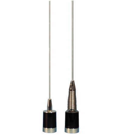
Broadband 1/2-wave antenna - no ground plane needed
- Manufactured using the best corrosion-resistant materials and finishes available
- Triple-plated chrome brass with a large insert, molded low-loss coil form and spring-loaded gold-plated contact
- Rubber boot ensures a moisture-proof installation/avoid scratching or rusting of the vehicle
-
Broadband 1/2-wave antenna - no ground plane needed
- Manufactured using the best corrosion-resistant materials and finishes available
- Triple-plated chrome brass with a large insert, molded low-loss coil form and spring-loaded gold-plated contact
- Rubber boot to ensure a moisture-proof installation/avoid scratching or rusting of the vehicle
-
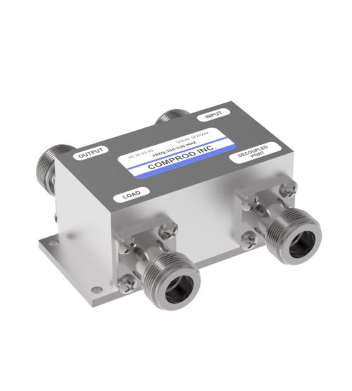
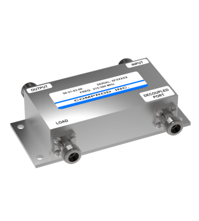
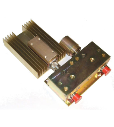
Bi-directional coupler, ideally suited for two-way communications systems
- Low insertion loss
- High isolation between ports
- Excellent VSWR
- Tri-band and other models are available and customizable.
-
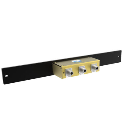
Designed for easy installation, reducing coaxial runs, and in-building applications with multi-band antennas
- Allows multiple bands to share the same transmission lines
- Available in VHF, UHF and 800/900 MHz bands
- Can be Tower-Mounted (TM), Rack-Mounted (RM) or stand alone
-
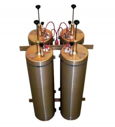
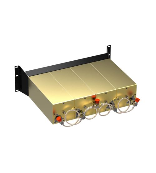
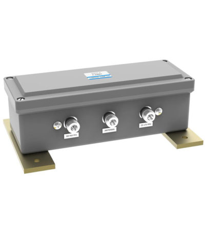
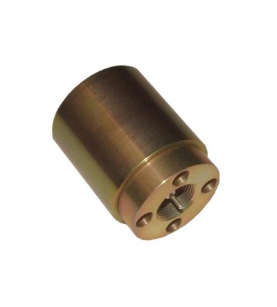
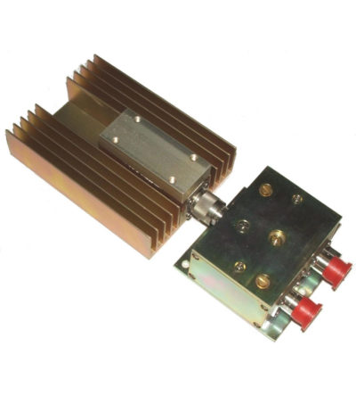
Designed for compact, close frequency installations. Ideal for very closely spaced frequency transmitters
- Ideal for intermodulation panels, providing extra protection with their second harmonic filters, when physical space is at a premium or is constrained, and for providing extra isolation between two very close transmitters
- High isolation: minimizes intermodulation products
- Low loss: maximizes system performance
- Continuous power:
- Physical size and materials used maximizes the performance across the operating band
-
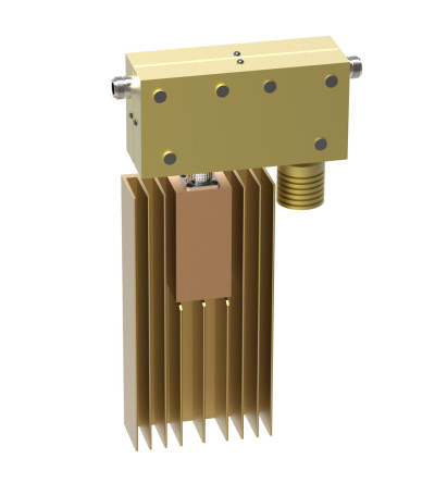
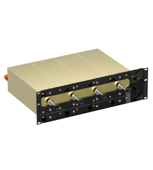
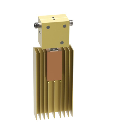
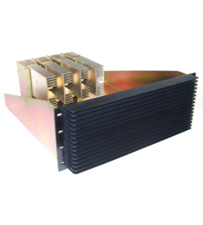
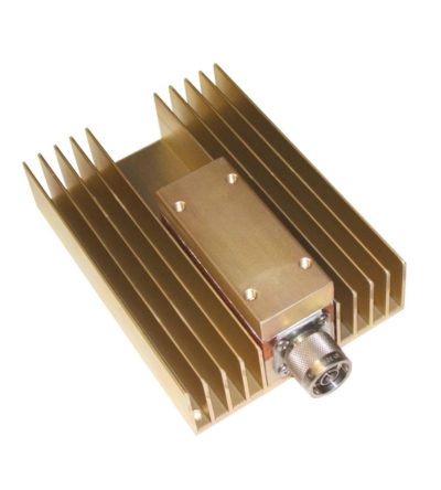
Specifically designed to continually absorb reflected power
- Excellent return loss
- Oversized heat sinks
- Continuous duty power:
- 24/7 operation
- Install-and-forget
-
Specifically designed to continually absorb reflected power
- Excellent return loss
- Oversized heat sinks
- Continuous duty power:
- 24/7 operation
- Install-and-forget
-
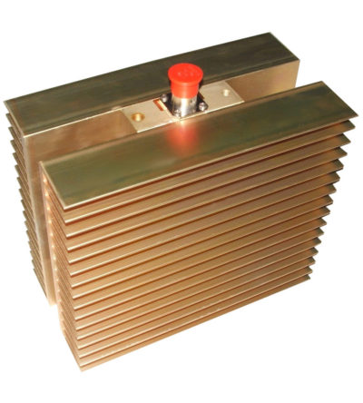
Specifically designed to continually absorb reflected power
- Excellent return loss
- Oversized heat sinks
- Continuous duty power:
- 24/7 operation
- Install-and-forget
-
Specifically designed to continually absorb reflected power
- Excellent return loss
- Oversized heat sinks
- Continuous duty power:
- 24/7 operation
- Install-and-forget
-
Specifically designed to continually absorb reflected power
- Excellent return loss
- Oversized heat sinks
- Continuous duty power:
- 24/7 operation
- Install-and-forget
-
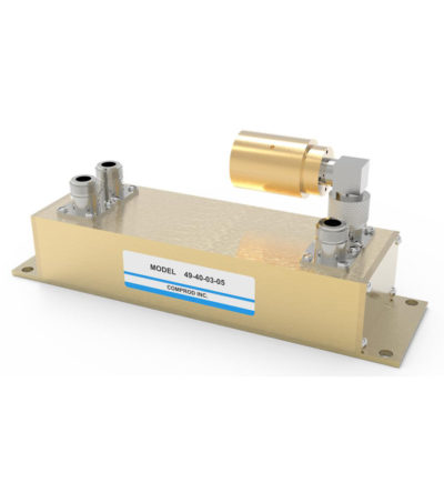
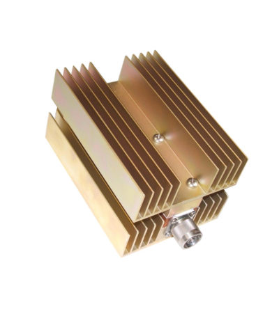
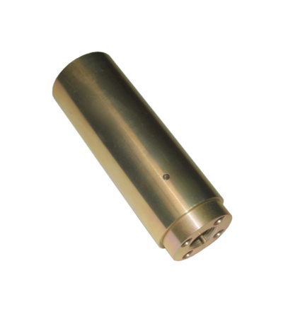
Ideal for blocking the transfer of RF power flow in the opposite direction
- Used for intermodulation panels, protecting your transmitters from reflected power and providing extra isolation
- High isolation: minimizes intermodulation products
- Low loss: maximizes system performance
- Continuous power: physical size and materials used maximize the performance across the operating band
- Can be combined with a variety of loads, 5/25/60/100/150/250 watt combinations, as well as with second harmonic filters for Hybrid Combiners (HTCs )
-
Ideal for combining multiple Rx frequencies onto the same antenna
- Available in 2, 4, 8, 12, 16 and 32 port configurations
- Simple and cost-effective design
- Standard 19” Rack Mount (RM) or cavity-mounted (CM) versions
- Each unit consists of a power splitter and an RF amplifier.
- Plug-in Power Supply (PS) optional
-
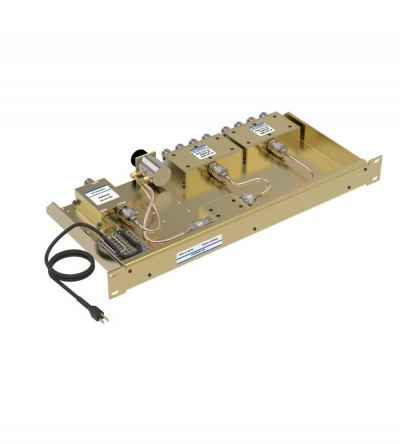
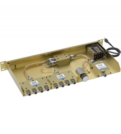
Incorporates expandability, close frequency spacing and some of the lowest insertion losses in the industry
- Can easily support 75 kHz Tx-Tx spacing or 50 kHz spacing while using 10” cavities
- Flexible design: from 1-21 channel capacity
- Expandable: 1 or more additional channels at a time; re-configurable equipment
- 132-174 MHz, 42 MHz of operating bandwidth
- Temperature compensation to ensure frequency stability
- High attenuation to minimize desense and interference
- Ultra-low insertion losses; low coupling and bridging losses
- Continuous high-power handling capability; 150 watts – 24/7
-
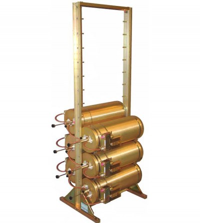
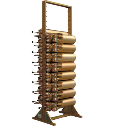
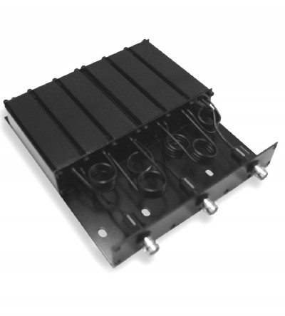
Designed for flexible, close frequency systems
- Each cavity has both a Reject and a Pass band curve
- Available in single units, they can be combined with band pass, notch, and pass reject cavities for added protection and isolation
- Temperature compensated to ensure frequency stability
- High attenuation to minimize desense and interference from adjacent systems
- Adjustable loops: each cavity has a calibration index for easy field tuning
-
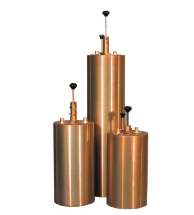
Features compact size, low loss and temperature compensation over the range of -40ºC to +60ºC
- Extruded aluminum cavities and solid- shield copper-jacketed inter-cabling that ensures excellent mechanical and electrical stability
- All units are adjustable in the field and rated at 50 watts continuous duty with a maximum VSWR of 1.5: 1 over the entire tuning range.
- BNC connectors are standard.