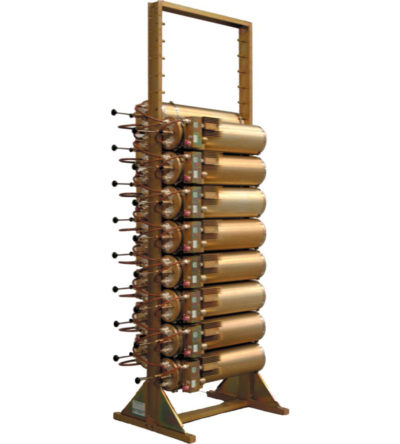
- Can easily support 125 kHz Tx-Tx spacing or 75 kHz spacing while using 10” cavities
- Flexible design: from 1-21 channel capacity
- Expandable: 1 or more additional channels at a time; re-configurable equipment
- 380-512 MHz, 132 MHz of operating bandwidth
- Temperature compensation to ensure frequency stability
- High attenuation to minimize desense and interference
- Ultra-low insertion losses; low coupling and bridging losses
- Continuous high-power handling capability; 150 watts – 24/7
-
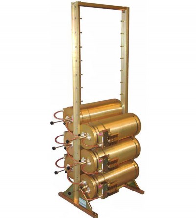
 Incorporates expandability, close frequency spacing and some of the lowest insertion losses in the industry
 -
Incorporates expandability, close frequency spacing and some of the lowest insertion losses in the industry
- Can easily support 125 kHz Tx-Tx spacing or 75 kHz spacing while using 10” cavities
- Flexible design: from 1-21 channel capacity
- Expandable: 1 or more additional channels at a time; re-configurable equipment
- 380-512 MHz, 132 MHz of operating bandwidth
- Temperature compensation to ensure frequency stability
- High attenuation to minimize desense and interference
- Ultra-low insertion losses; low coupling and bridging losses
- Continuous high-power handling capability; 150 watts – 24/7
-
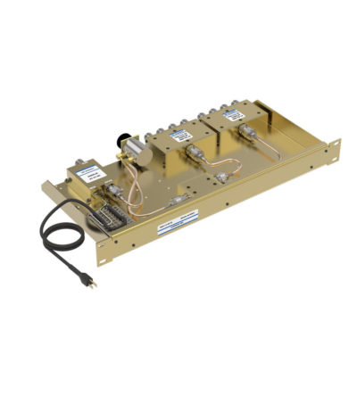
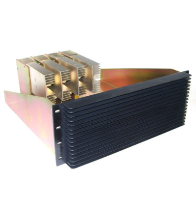
Ideal for combining multiple Rx frequencies onto the same antenna
- Available in 2, 4, 8, 12 , 16 and 32 port configurations
- Simple and cost-effective design
- Standard 19” Rack Mount (RM) or cavity-mounted (CM) versions
- Each unit consists of a power splitter and an RF amplifier.
- Plug-in Power Supply (PS) optional
-
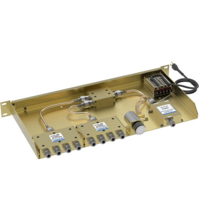
Combines multiple receiver frequencies onto the same antenna
- A low noise amplifier provides gain across the frequency band
- Low noise figure and low intermodulation generation
- Features up to 16 ports (24 and 32 port versions are available)
- -30 dB signal sampler port that can also be used to inject a signal
-
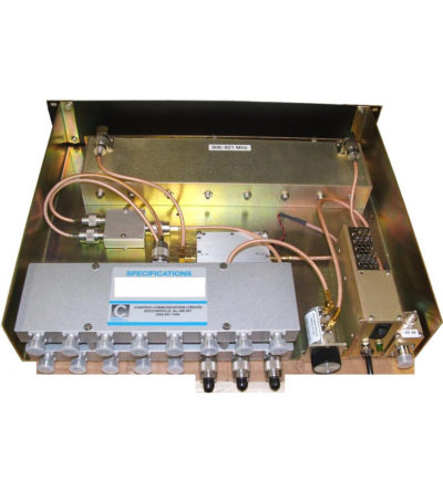
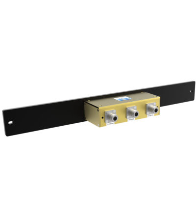
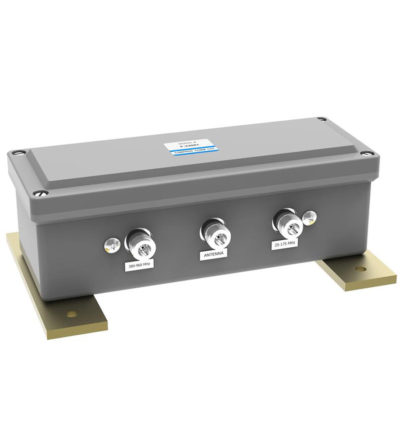
Designed for easy installation, reducing coaxial runs, and in-building applications with multi-band antennas
- Allows multiple bands to share the same transmission lines
- Available in VHF, UHF and 800/900 MHz bands
- Can be Tower-Mounted (TM), Rack-Mounted (RM) or stand alone
-
Designed for easy installation, reducing coaxial runs, and in-building applications with multi-band antennas
- Allows multiple bands to share the same transmission lines
- Available in VHF, UHF and 800/900 MHz bands
- Can be Tower-Mounted (TM), Rack-Mounted (RM) or stand alone
-
Fully expandable and reconfigurable
- Features X-Pass, plug-and-play technology
- Designed to offer engineers and technicians many options when designing or upgrading a site
-
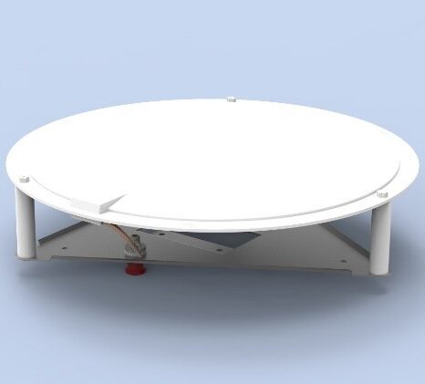
Usage for Distributed Antenna Systems (DAS) for Public Safety or LTE communication in multiple stories of a building.
- Mounting on a ceiling or gyprock wall, without need of a ground plane
-
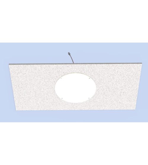
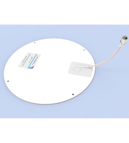
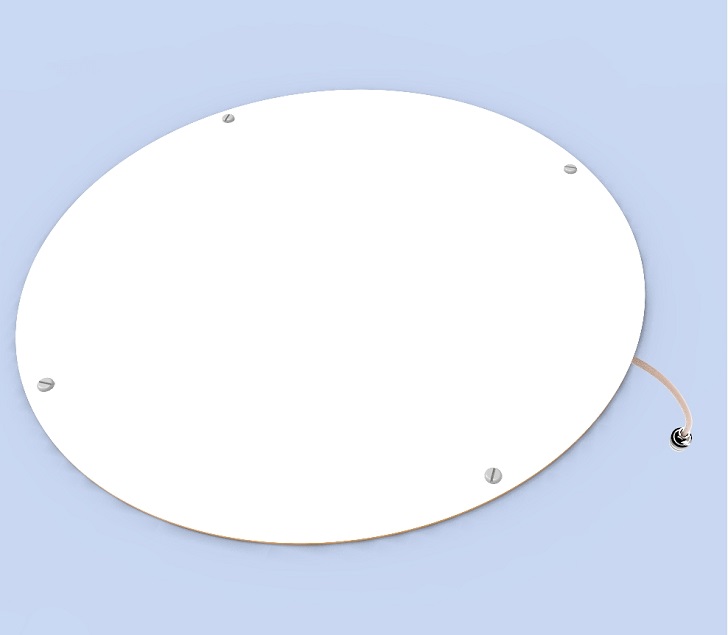
Produc short description before changes Usage for Distributed Antenna Systems (DAS) for Public Safety or LTE communication in multiple stories of a building. The antenna’s main application includes usage for:
- Distributed Antenna Systems (DAS) for Public Safety
- LTE communication
- Cellular bands in multiple stories of a building
- Mounting on a ceiling or gyprock wall, without need of a ground plane
-
Usage for Distributed Antenna Systems (DAS) for Public Safety or LTE communication in multiple stories of a building.
- Designed to be installed on hard surfaces such as concrete or metal structures.
- A layer of Kydex 6200 of 0.3’’ thickness is added to meet the recommended fire safety practices of both the Federal Transit Administration (FTA) and the Federal Rail Administration (FRA) for smoke emission and flammability as tested under ASTM E-662 and ASTM E-162
-
Usage for Distributed Antenna Systems (DAS) for Public Safety or LTE communication in multiple stories of a building.
- Mounting on a ceiling or gyprock wall, without need of a ground plane
- An extra protection can be added to meet the recommended fire safety practices of both the Federal Transit Administration (FTA) and the Federal Rail Administration (FRA) for smoke emission and flammability as tested under ASTM E-662 and ASTM E-162
-
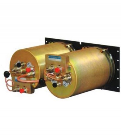
Designed for compact, close frequency installations. Ideal for very closely spaced frequency transmitters
- Ideal for intermodulation panels, providing extra protection with their second harmonic filters, when physical space is at a premium or is constrained, and for providing extra isolation between two very close transmitters
- High isolation: minimizes intermodulation products
- Low loss: maximizes system performance
- Continuous power:
- Physical size and materials used maximizes the performance across the operating band