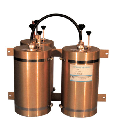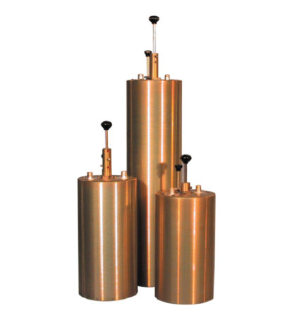
- Available in single, dual, triple or additional units
- Temperature compensated to ensure frequency stability
- High attenuation to minimize desense and interference from adjacent systems
- Adjustable loops: each cavity has a calibration index for easy field tuning
-
 Designed for minimizing interference from adjacent channels and outside systems
 -
Designed for minimizing interference from adjacent channels and outside systems
- Available in single, dual, triple or additional units
- Temperature compensated to ensure frequency stability
- High attenuation to minimize desense and interference from adjacent systems
- Adjustable loops: each cavity has a calibration index for easy field tuning
-
Designed to minimize interference from adjacent channels and outside systems
- Available in single, dual or triple units
- Temperature compensated to ensure frequency stability
- High attenuation
- Adjustable loops: each cavity has a calibration index to reference insertion loss
-
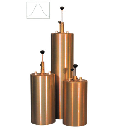
Designed to pass a frequency band and reject a narrow band of frequencies
- Can reject frequencies on either the high or low side of the pass frequency
- Temperature compensated to ensure frequency stability
- High attenuation to minimize desense and interference
-
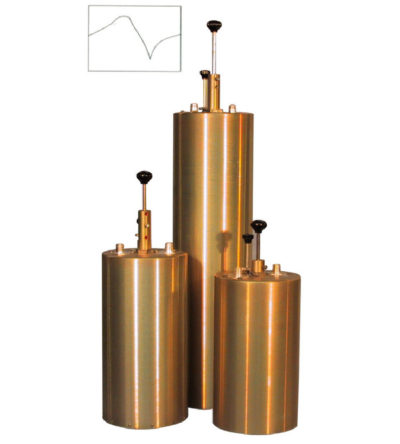
Designed to reject one narrow band of frequencies, while letting all others pass in the operating band
- Can be cascaded or added to one another in order to sharpen the attenuation of the rejection curve
- Temperature compensated to ensure frequency stability
- High attenuation to minimize desense and interference from adjacent systems
- Adjustable loops: each cavity has a calibration index
-
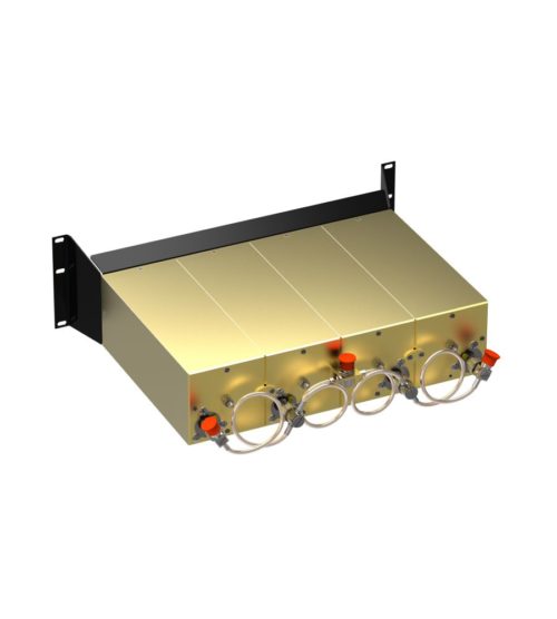
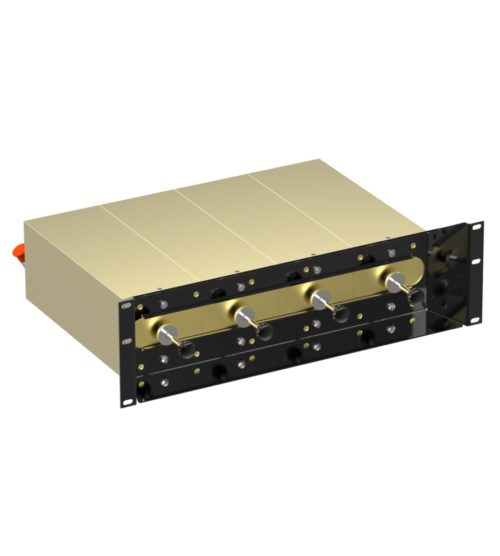
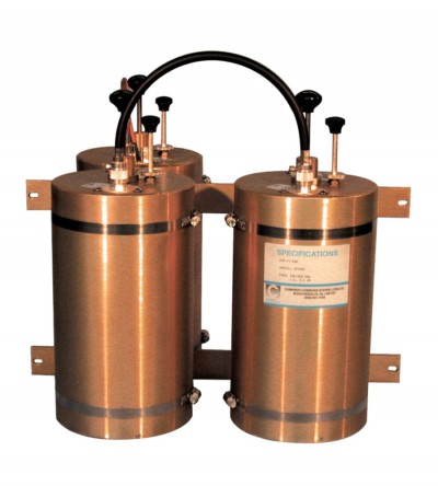
Ideal for compact high performance applications
- Designed for the combination of two frequencies that require extra isolation. Can also be used as efficient pre-selectors
- An eight cavity configuration is also available for a higher level of isolation and selectivity
- Can be retuned in the field
-
Designed for flexible, close frequency systems
- Each cavity has both a Reject and a Pass band curve
- Available in single units, they can be combined with band pass, notch, and pass reject cavities for added protection and isolation
- Temperature compensated to ensure frequency stability
- High attenuation to minimize desense and interference from adjacent systems
- Adjustable loops: each cavity has a calibration index for easy field tuning
-
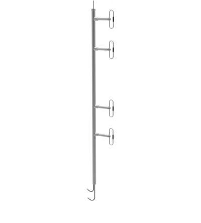
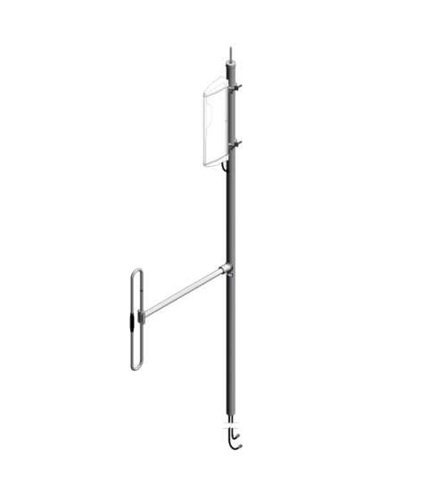
Adjustable or fixed, side mount or top mount antenna
- Available in 1, 2, 4, 8 and dual dipole configurations
- Offered in a 1/4, 3/8, or 1/2 wave versions
- Internal cabling and fixed dipole-mast spacing
- Heavy-duty and black anodized versions available
-
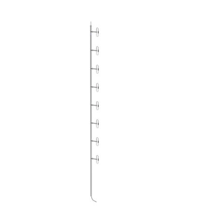
Adjustable or fixed, side mount or top mount antenna
- Available in 1, 2, 4, 8 and dual dipole configurations
- Offered in a 1/4, 3/8, or 1/2 wave versions
- Internal cabling and fixed dipole-mast spacing
- Heavy-duty and black anodized versions available
-
Adjustable or fixed, side mount or top mount antenna
- Available in 1, 2, 4, 8 and dual dipole configurations
- Offered in a 1/4, 3/8, or 1/2 wave versions
- Internal cabling and fixed dipole-mast spacing
- Heavy-duty and black anodized versions available
-
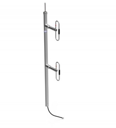
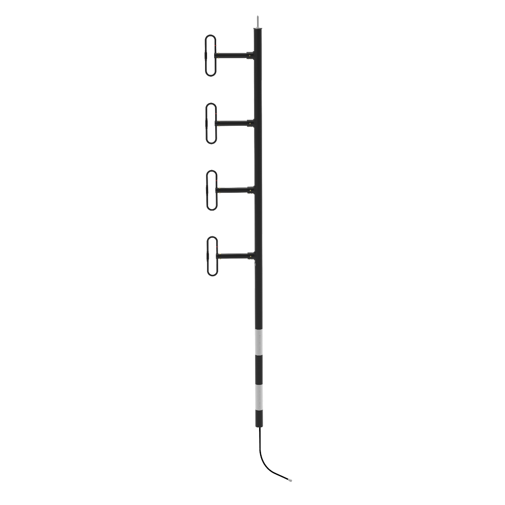
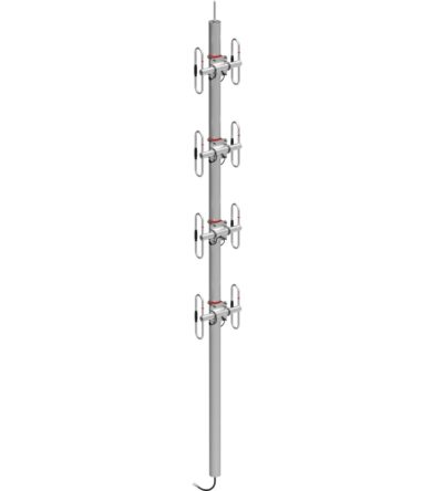
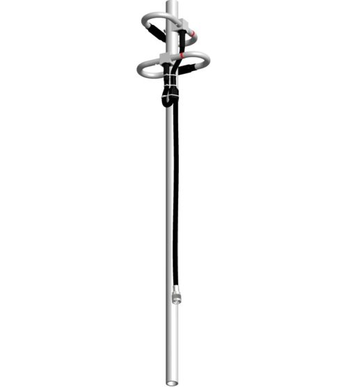
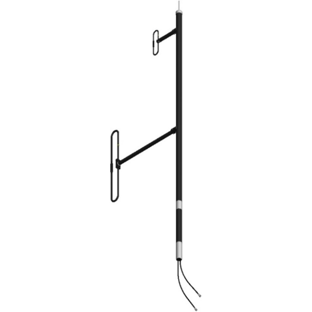
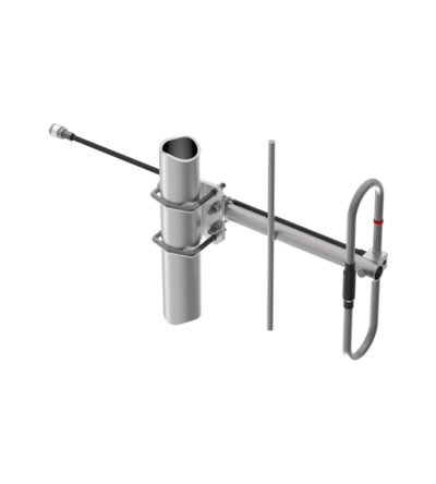
The 774-70-HDBWTM-1/2 is a Wide Band, Black Anodized, Heavy Duty Welded, UHF Antenna. It is an extremely rugged 4 dipole Antenna designed for multicoupled systems. All our antennas can be customized to your particular applications. Our antennas can be configured for side mount or top mount. This antenna is configured for top mount. The 774-70-HDBWTM-1/2 antenna has internal cabling and fixed dipole-mast spacing. The antenna has either 406-470 MHz or 450-512 MHz split.
- Low VSWR version with maximum gain over specified frequency.
- Heavy Duty and Black Anodized version.
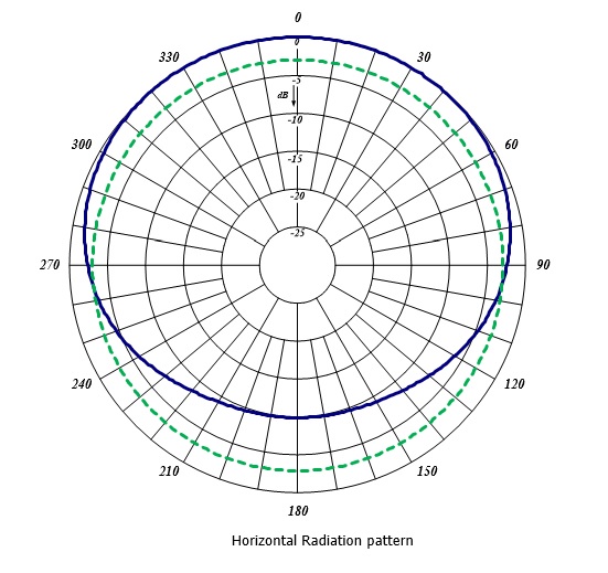
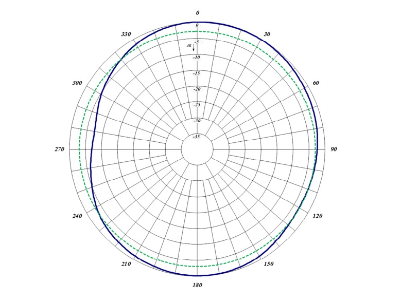
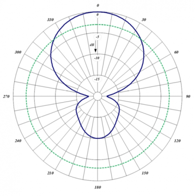
- This antenna is 1/2 wavelength spacing version offering bidirectional radiation pattern.
- Standard connector is N-Male and optional 7/16 DIN or 4.3-10 is also available.
-
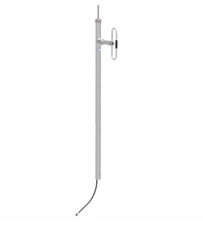
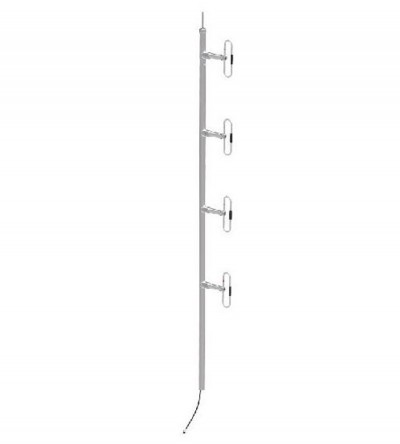
The 774-70-HDBWTM-1/4 is a Wide Band, Black Anodized, Heavy Duty Welded, UHF Antenna. It is an extremely rugged 4 dipole Antenna designed for multicoupled systems. All our antennas can be customized to your particular applications. Our antennas can be configured for side mount or top mount. This antenna is configured for top mount. The 774-70-HDBWTM-1/4 antenna has internal cabling and fixed dipole-mast spacing. The antenna has either 406-470 MHz or 450-512 MHz split.
- Low VSWR version with maximum gain over specified frequency.
- Heavy Duty and Black Anodized version.
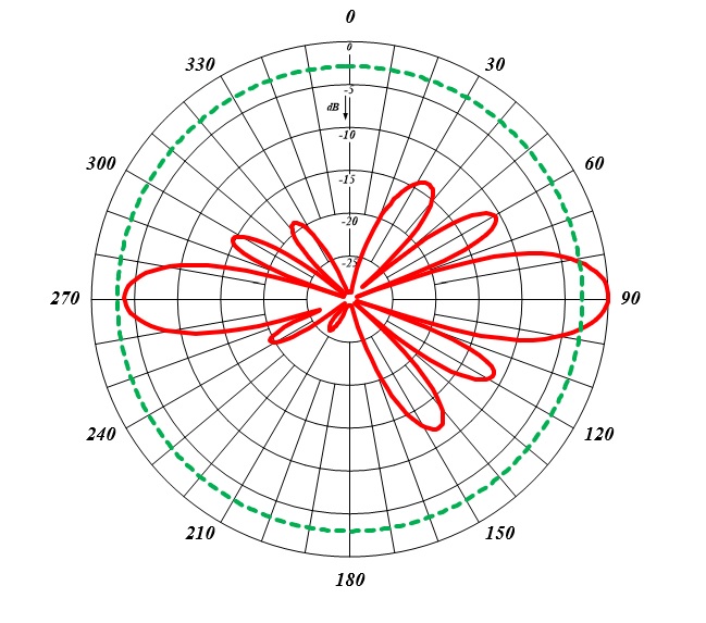
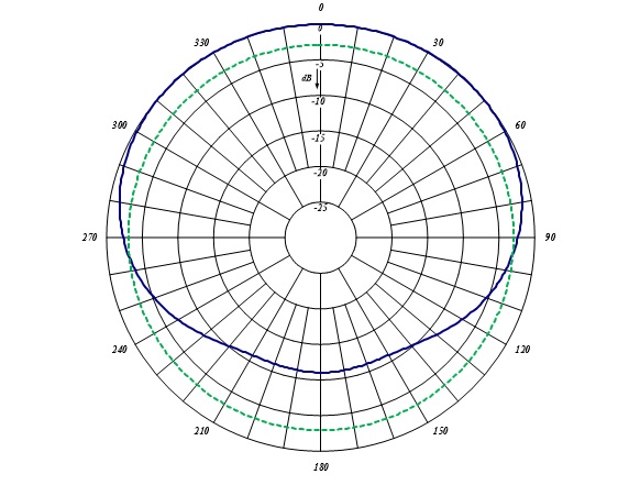
- This antenna is 1/4 wavelength spacing version offering offset radiation pattern.
- Standard connector is N-Male and optional 7/16 DIN or 4.3-10 is also available.
-
DOWNLOAD PDF DOWNLOAD DIGITAL PATTERNSIdeal for applications where costs are calculated per antenna
- Available in many configurations
- VHF, UHF or 700/800/900 MHz antennas can be combined onto one mast
- Mix and match with our 770, 790, 840, 870 and 880 series antennas
- Can be configured for side or top mount
- Low VSWR version with maximum gain over specified frequency
- Certain versions of antennas have an adjustable pattern for 3 dBd omnidirectional or 6 dBd offset coverage
- Heavy-duty versions available
-
Adjustable or fixed, side mount or top mount antenna
- Available in 1, 2, 4, 8 and dual dipole configurations
- Offered in a 1/4, 3/8, or 1/2 wave versions
- Internal cabling and fixed dipole-mast spacing
- Heavy-duty and black anodized versions available
-
DOWNLOAD PDF DOWNLOAD DIGITAL PATTERNSOffered in Omni or bi-directional versions
- Available in 2 and 4 dipole set configurations
- Complete internal cabling, fixed dipole-mast spacing, and adjustable pattern control
- Heavy-duty, black anodized and top mount configuration only versions available
-
Offered in Omni or bi-directional versions
- Available in 2 and 4 dipole set configurations
- Complete internal cabling, fixed dipole-mast spacing, and adjustable pattern control
- Heavy-duty, black anodized and top mount configuration only versions available
-
Constructed from high strength, corrosion resistant aluminum alloy and stainless steel
- Available in VHF, UHF, 800/900 MHz configurations
- Rugged design to withstand harsh environmental conditions
- Circular polarization
- DC ground for lightning protection
-
Ideal for applications where costs are calculated per antenna
- Available in many configurations
- VHF, UHF or 700/800/900 MHz antennas can be combined onto one mast
- Mix and match with our 770, 790 and 870 series antennas
- Can be configured for side or top mount
- Low VSWR version with maximum gain over the specified frequencies
- Heavy-duty versions available
-
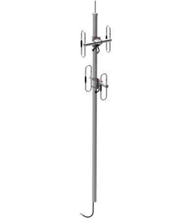
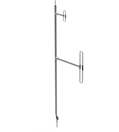
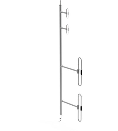
The F-3647 is a wideband dual antenna with an 871F-70 on the base and a 771-70 on the top. The antenna offers for the 871F-70 & 771-70 a choice of radiation patterns that are determined by the dipole-to-mast spacing. The F-3647 has an internal cabling and is not field adjustable. The 871F-70 & 771-70 antenna is offered in a ¼, 3/8, or ½ wave pattern spacing versions. The antenna can be black anodized. Heavy Duty version of the antenna is also available. DOWNLOAD PDF DOWNLOAD DIGITAL PATTERNS
-
The F-3647 is a heavy duty wideband dual antenna with an 871F-70 on the base and a 771-70 on the top. The antenna offers for the 871F-70 & 771-70 a choice of radiation patterns that are determined by the dipole-to-mast spacing. The F-3647 has an internal cabling and is not field adjustable. The 871F-70 & 771-70 antenna is offered in a ¼, 3/8, or ½ wave pattern spacing versions. The antenna can be black anodized. Heavy Duty version of the antenna is also available. DOWNLOAD PDF DOWNLOAD DIGITAL PATTERNS
-
Ideal for applications where costs are calculated per antenna
- Available in many configurations
- VHF, UHF or 700/800/900 MHz antennas can be combined onto one mast
- Mix and match with our 770, 790 and 870 series antennas
- Can be configured for side or top mount
- Low VSWR version with maximum gain over the specified frequencies
- Heavy-duty versions available
-
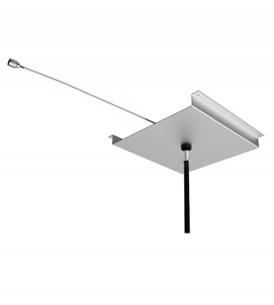
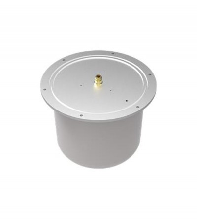
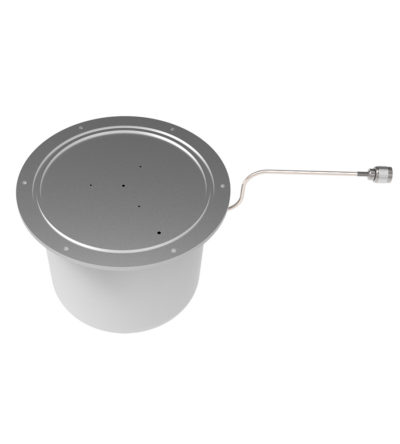
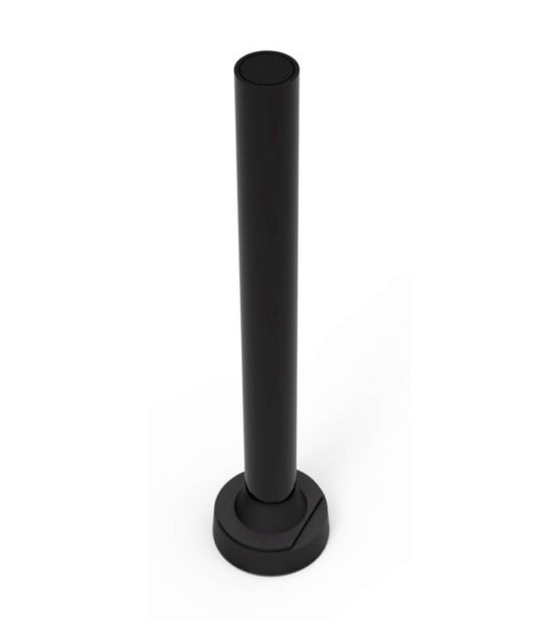
Designed for external Public Safety Radio Frequencies to propagate within buildings, tunnels or public use environments
- Designed for mounting on a concrete surface to meet full bandwidth specifications
- Meet the recommended fire safety practices of both the Federal Transit Administration (FTA) and the Federal Rail Administration (FRA) for smoke emission and flammability as tested under ASTM E-662 and ASTM E-162
- Flame resistant and self-extinguishing polycarbonate tubing is used for the radome
-
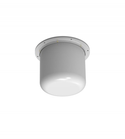
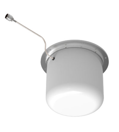
Designed for external Public Safety Radio Frequencies to propagate within buildings, tunnels or public use environments
- Offered with Fire Retardant 6200 Kydex
- Meet the recommended fire safety practices of both the Federal Transit Administration (FTA) and the Federal Rail Administration (FRA) for smoke emission and flammability as tested under ASTM E-662 and ASTM E-162
- The F-3749 Antenna is available in custom colors for orders of 150 or more.
-
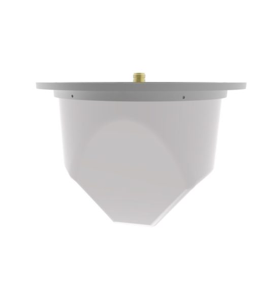
Designed for external Public Safety Radio Frequencies to propagate within buildings, tunnels or public use environments
- Offered with Fire Retardant 6200 Kydex
- Meets the recommended fire safety practices of both the Federal Transit Administration (FTA) and the Federal Rail Administration (FRA) for smoke emission and flammability as tested under ASTM E-662 and ASTM E-162
- The F-3749B Antenna is available in custom colors for orders of 150 or more.
-
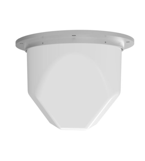
Designed for external Public Safety Radio Frequencies to propagate within buildings, tunnels or public use environments
- Offered with Fire Retardant 6200 Kydex
- Meet the recommended fire safety practices of both the Federal Transit Administration (FTA) and the Federal Rail Administration (FRA) for smoke emission and flammability as tested under ASTM E-662 and ASTM E-162
-
Rugged design to withstand harsh environmental conditions
- Available in the UHF configuration (3 frequency splits)
- Available in 2, 3, 7 element and 70 MHz wideband configurations
- Vertical or horizontal polarization
- DC ground for lightning protection
- Fully welded for added durability
- Black anodized and heavy-duty versions available
-
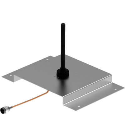
Designed for external Public Safety Radio Frequencies to propagate within buildings, tunnels or public use environments
- Multiple frequency bands
- Aluminum painted
-
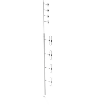
The F-3980 is a wide band dual antenna with an 871F-70 on the base and a 792-70 on the top. The antenna offers for the 871F-70 a choice of radiation patterns that are determined by the dipole-to-mast spacing. The F-3980 has an internal cabling and is not field adjustable. The 871F-70 antenna is offered in a ¼, 3/8, or ½ wave pattern spacing versions. SPEC Sheet
-
Designed for external Public Safety Radio Frequencies to propagate within buildings, tunnels or public use environments
- Aluminium painted
-
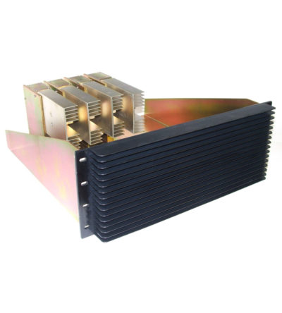
Designed for compact, close frequency installations. Ideal for very closely spaced frequency transmitters
- Ideal for intermodulation panels, providing extra protection with their second harmonic filters, when physical space is at a premium or is constrained, and for providing extra isolation between two very close transmitters
- High isolation: minimizes intermodulation products
- Low loss: maximizes system performance
- Continuous power:
- Physical size and materials used maximizes the performance across the operating band
-
Designed for compact, close frequency installations. Ideal for very closely spaced frequency transmitters
- Ideal for intermodulation panels, providing extra protection with their second harmonic filters, when physical space is at a premium or is constrained, and for providing extra isolation between two very close transmitters
- High isolation: minimizes intermodulation products
- Low loss: maximizes system performance
- Continuous power:
- Physical size and materials used maximizes the performance across the operating band