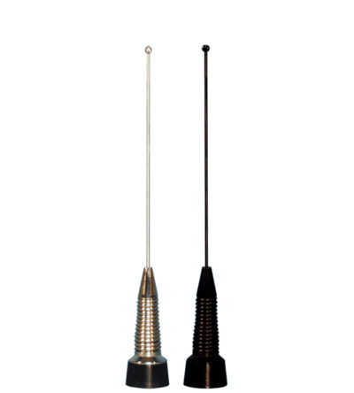
- Manufactured using the best corrosion-resistant materials and finishes available
- Integrated shock spring and a heavy-duty stainless steel whip that is designed to withstand severe shock
- Ultrasonically-welded brass insert and a gold-plated spring-loaded contact
- Provides 24 MHz of bandwidth using VHF frequencies and 100 MHz of bandwidth at UHF frequencies
- Standard Motorola C, M type mount
-
 Unity gain in a broadband design for extra heavy-duty service
 -
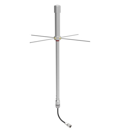
 Designed for external Public Safety Radio Frequencies to propagate within buildings, tunnels or public use environments
- Multiple frequency bands
- Aluminum painted
-

 Very large bandwidth which make it ideal for emergency use or resale
- Available in UHF configuration (3 frequency splits)
- Rugged design to withstand the most extreme environmental conditions
- The mounting hardware supplied will permit 0.75” to 2.3/8” O.D. pipe installation.
- DC ground for lightning protection
-
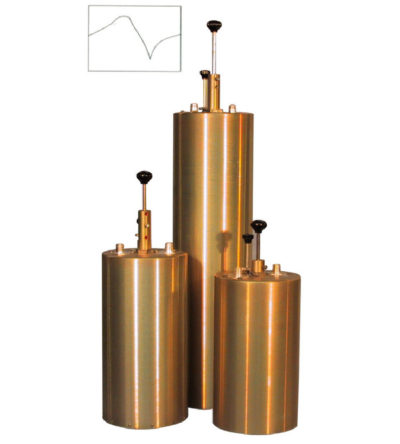
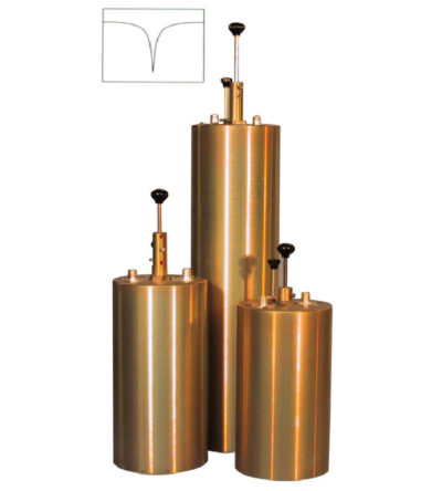
 Designed to pass a frequency band and reject a narrow band of frequencies
- Can reject frequencies on either the high or low side of the pass frequency
- Temperature compensated to ensure frequency stability
- High attenuation to minimize desense and interference
-
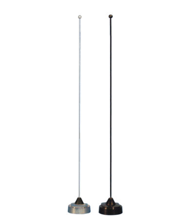
 Unity gain in a wideband design for heavy-duty service
- Manufactured using the best corrosion-resistant materials and finishes available
- Ultrasonically-welded brass insert and a gold-plated spring-loaded contact
- Shipped with a factory tuned whip cut to size based on the customer specified frequency range between 136 MHz and 960 MHz
- Standard Motorola NMO type mount providing an excellent moisture seal even when the antenna is removed
-
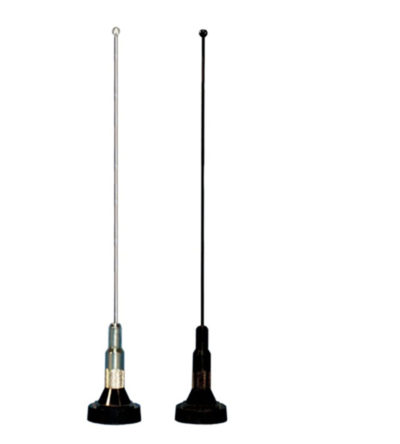
 Unity gain in a wideband design for heavy-duty service
- Manufactured using the best corrosion-resistant materials and finishes available
- Ultrasonically-welded brass insert and a gold-plated spring-loaded contact
- Shipped with a 19” whip that can be cut by the customer to any frequency between 136 MHz and 960 MHz
- Standard Motorola NMO type mount providing an excellent moisture seal even when the antenna is removed
-

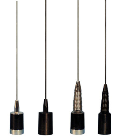
- 3.0 dBd gain achieved by featuring a 5/8-wave whip with a base loaded matching coil
- Manufactured using the best corrosion-resistant materials and finishes available
- Triple-plated chrome brass with a large insert molded low-loss coil form and spring-loaded, gold-plated contact
- Large diameter coil form which allows for a wider operational bandwidth and better matching characteristics
- Rubber boot and overlap construction to ensure a moisture-proof installation
- Standard Motorola NMO type mount
-
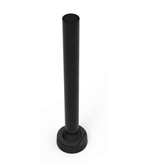
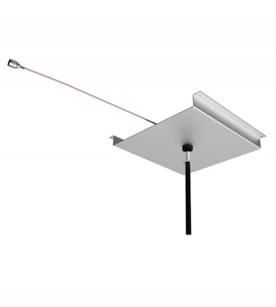
 Designed for external Public Safety Radio Frequencies to propagate within buildings, tunnels or public use environments
- Designed for mounting on a concrete surface to meet full bandwidth specifications
- Meet the recommended fire safety practices of both the Federal Transit Administration (FTA) and the Federal Rail Administration (FRA) for smoke emission and flammability as tested under ASTM E-662 and ASTM E-162
- Flame resistant and self-extinguishing polycarbonate tubing is used for the radome
-
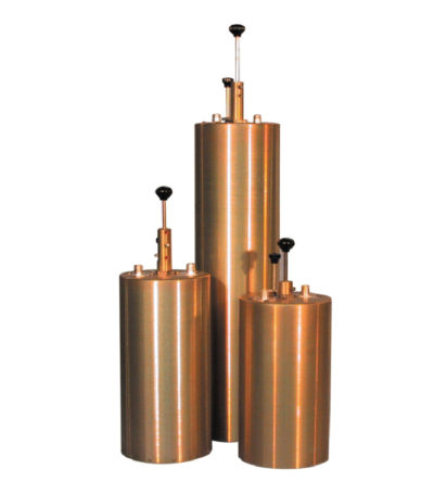
 Designed to reject one narrow band of frequencies, while letting all others pass in the operating band
- Can be cascaded or added to one another in order to sharpen the attenuation of the rejection curve
- Temperature compensated to ensure frequency stability
- High attenuation to minimize desense and interference from adjacent systems
- Adjustable loops: each cavity has a calibration index
-
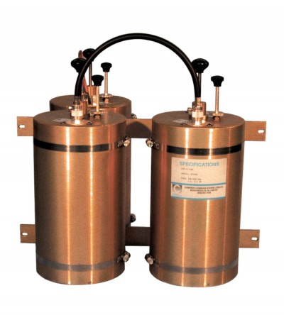
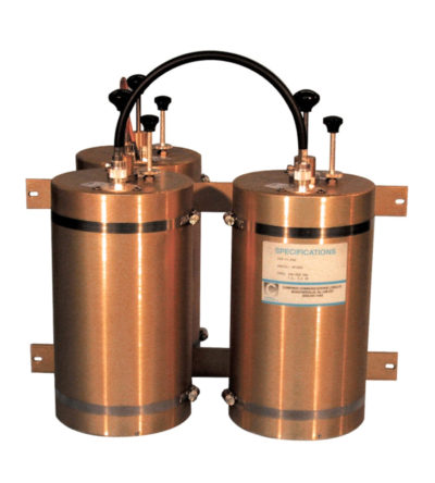
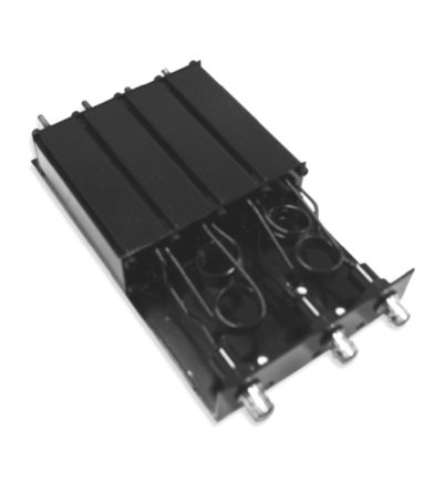
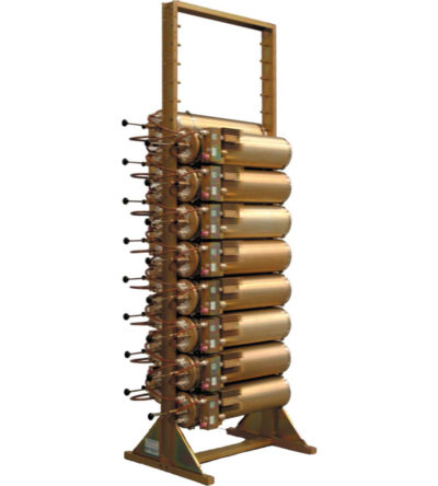
 Designed for minimizing interference from adjacent channels and outside systems
- Available in single, dual, triple or additional units
- Temperature compensated to ensure frequency stability
- High attenuation to minimize desense and interference from adjacent systems
- Adjustable loops: each cavity has a calibration index for easy field tuning
-
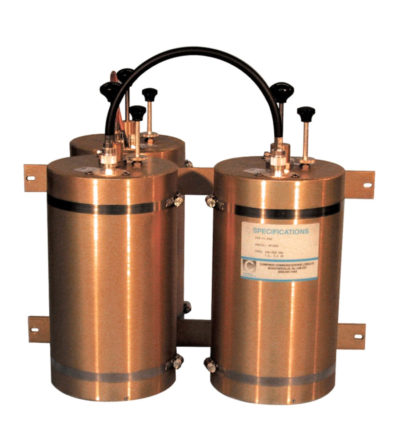
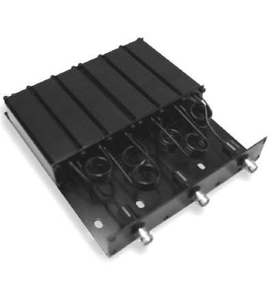
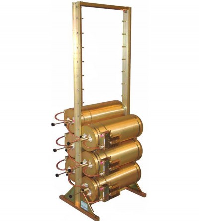
 Designed for minimizing interference from adjacent channels and outside systems
- Available in single, dual, triple or additional units
- Temperature compensated to ensure frequency stability
- High attenuation to minimize desense and interference from adjacent systems
- Adjustable loops: each cavity has a calibration index for easy field tuning
-
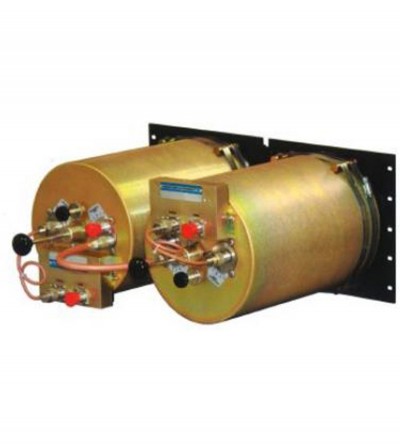
 Designed for minimizing interference from adjacent channels and outside systems
- Available in single, dual, triple or additional units
- Temperature compensated to ensure frequency stability
- High attenuation to minimize desense and interference from adjacent systems
- Adjustable loops: each cavity has a calibration index for easy field tuning
-

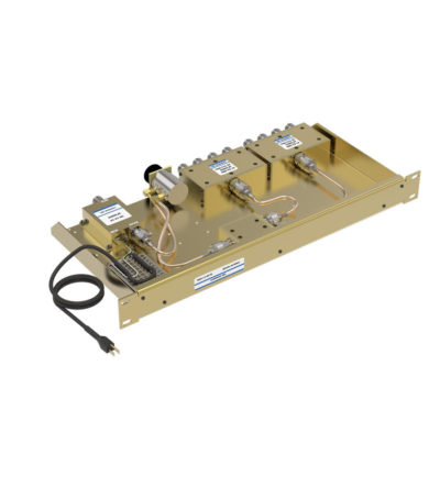
 Ideal for compact high performance applications
- Designed for the combination of two frequencies that require extra isolation. Can also be used as efficient pre-selectors
- An eight cavity configuration is also available for a higher level of isolation and selectivity
- Can be retuned in the field
-
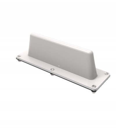
 Ideal for low clearance applications such as those found on trains, public transit vehicles, construction equipment and police vehicles
- Low-profile rugged alternative to a ¼-wave whip mobile antenna
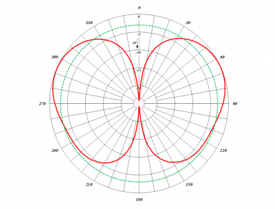
- When mounted on a horizontal surface, maximum radiation is omnidirectional and vertically polarized
- High strength cast aluminum design. Can be coated for additional protection against harsh environmental conditions
- Supplied with an O-ring to ensure a moisture-proof installation
-
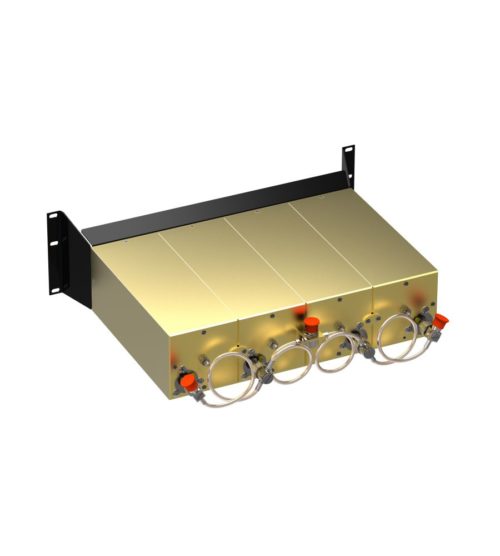
 Features compact size, low loss and temperature compensation over the range of -40ºC to +60ºC
- Extruded aluminum cavities and solid- shield copper-jacketed inter-cabling that ensures excellent mechanical and electrical stability
- All units are adjustable in the field and rated at 50 Watts maximum with a maximum VSWR of 1.5: 1 over the entire tuning range.
- BNC connectors are standard.
-
 Ideal for low clearance applications such as those found on trains, public transit vehicles, construction equipment and police vehicles
- Low-profile rugged alternative to a ¼-wave whip mobile antenna
- When mounted on a horizontal surface, maximum radiation is omnidirectional and vertically polarized
- Impact-resistant ABS radome
- Supplied with a mounting gasket to ensure a moisture-proof installation
-
 Features compact size, low loss and temperature compensation over the range of -40ºC to +60ºC
- Extruded aluminum cavities and solid- shield copper-jacketed inter-cabling that ensures excellent mechanical and electrical stability
- All units are adjustable in the field and rated at 50 watts continuous duty with a maximum VSWR of 1.5: 1 over the entire tuning range.
- BNC connectors are standard.
-

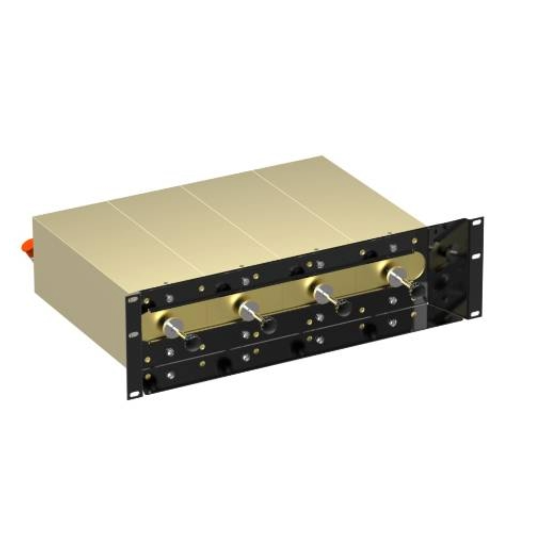
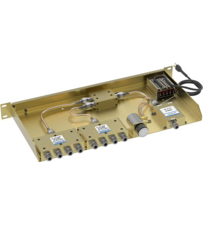
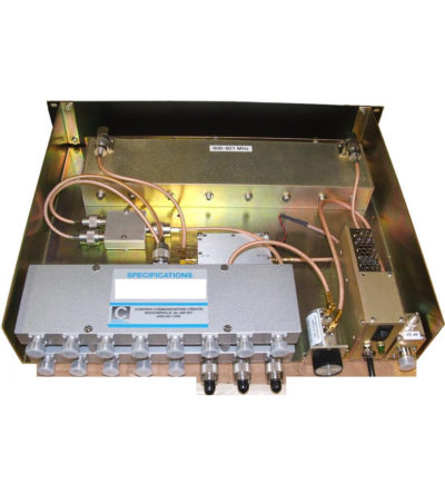
 Ideal for combining multiple Rx frequencies onto the same antenna
- Available in 2, 4, 8, 12 , 16 and 32 port configurations
- Simple and cost-effective design
- Standard 19” Rack Mount (RM) or cavity-mounted (CM) versions
- Each unit consists of a power splitter and an RF amplifier.
- Plug-in Power Supply (PS) optional
-
 Combines multiple receiver frequencies onto the same antenna
- A low noise amplifier provides gain across the frequency band
- Low noise figure and low intermodulation generation
- Features up to 16 ports (24 and 32 port versions are available)
- -30 dB signal sampler port that can also be used to inject a signal
-
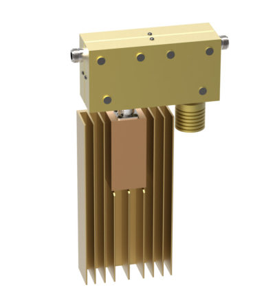
 Ideal for blocking the transfer of RF power flow in the opposite direction
- Used for intermodulation panels, protecting your transmitters from reflected power and providing extra isolation
- High isolation: minimizes intermodulation products
- Low loss: maximizes system performance
- Continuous power: physical size and materials used maximize the performance across the operating band
- Can be combined with a variety of loads, 5/25/60/100/150/250 watt combinations, as well as with second harmonic filters for Hybrid Combiners (HTCs )
-
 Ideal for blocking the transfer of RF power flow in the opposite direction
- Used for intermodulation panels, protecting your transmitters from reflected power and providing extra isolation
- High isolation: minimizes intermodulation products
- Low loss: maximizes system performance
- Continuous power: physical size and materials used maximize the performance across the operating band
- Can be combined with a variety of loads, 5/25/60/100/150/250 watt combinations, as well as with second harmonic filters for Hybrid Combiners (HTCs )
-
 Ideal for blocking the transfer of RF power flow in the opposite direction
- Used for intermodulation panels, protecting your transmitters from reflected power and providing extra isolation
- High isolation: minimizes intermodulation products
- Low loss: maximizes system performance
- Continuous power: physical size and materials used maximize the performance across the operating band
- Can be combined with a variety of loads, 5/25/60/100/150/250 watt combinations, as well as with second harmonic filters for Hybrid Combiners (HTCs )
-
 Ideal for blocking the transfer of RF power flow in the opposite direction
- Used for intermodulation panels, protecting your transmitters from reflected power and providing extra isolation
- High isolation: minimizes intermodulation products
- Low loss: maximizes system performance
- Continuous power: physical size and materials used maximize the performance across the operating band
- Can be combined with a variety of loads, 5/25/60/100/150/250 watt combinations, as well as with second harmonic filters for Hybrid Combiners (HTCs )
-
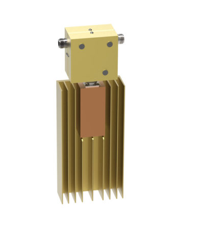
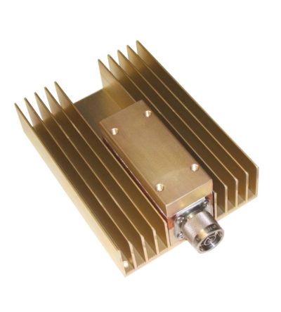
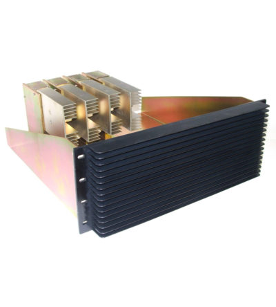
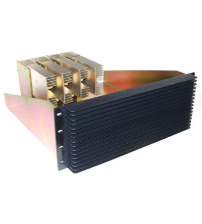
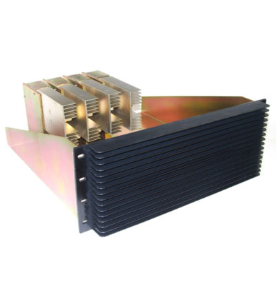
 Specifically designed to continually absorb reflected power
- Excellent return loss
- Oversized heat sinks
- Continuous duty power:
- 24/7 operation
- Install-and-forget
-
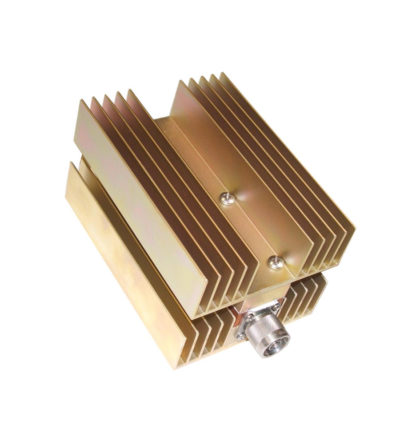
 Specifically designed to continually absorb reflected power
- Excellent return loss
- Oversized heat sinks
- Continuous duty power:
- 24/7 operation
- Install-and-forget
-
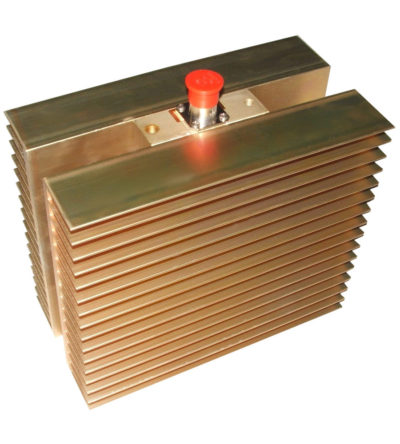
 Specifically designed to continually absorb reflected power
- Excellent return loss
- Oversized heat sinks
- Continuous duty power:
- 24/7 operation
- Install-and-forget
-
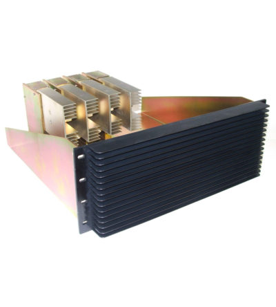
 Specifically designed to continually absorb reflected power
- Excellent return loss
- Oversized heat sinks
- Continuous duty power:
- 24/7 operation
- Install-and-forget
-
 Specifically designed to continually absorb reflected power
- Excellent return loss
- Oversized heat sinks
- Continuous duty power:
- 24/7 operation
- Install-and-forget
-
 Designed for compact, close frequency installations. Ideal for very closely spaced frequency transmitters
- Ideal for intermodulation panels, providing extra protection with their second harmonic filters, when physical space is at a premium or is constrained, and for providing extra isolation between two very close transmitters
- High isolation: minimizes intermodulation products
- Low loss: maximizes system performance
- Continuous power:
- Physical size and materials used maximizes the performance across the operating band
-
 Designed for compact, close frequency installations. Ideal for very closely spaced frequency transmitters
- Ideal for intermodulation panels, providing extra protection with their second harmonic filters, when physical space is at a premium or is constrained, and for providing extra isolation between two very close transmitters
- High isolation: minimizes intermodulation products
- Low loss: maximizes system performance
- Continuous power:
- Physical size and materials used maximizes the performance across the operating band
-
 Designed for compact, close frequency installations. Ideal for very closely spaced frequency transmitters
- Ideal for intermodulation panels, providing extra protection with their second harmonic filters, when physical space is at a premium or is constrained, and for providing extra isolation between two very close transmitters
- High isolation: minimizes intermodulation products
- Low loss: maximizes system performance
- Continuous power:
- Physical size and materials used maximizes the performance across the operating band
-
 Designed for compact, close frequency installations. Ideal for very closely spaced frequency transmitters
- Ideal for intermodulation panels, providing extra protection with their second harmonic filters, when physical space is at a premium or is constrained, and for providing extra isolation between two very close transmitters
- High isolation: minimizes intermodulation products
- Low loss: maximizes system performance
- Continuous power:
- Physical size and materials used maximizes the performance across the operating band

