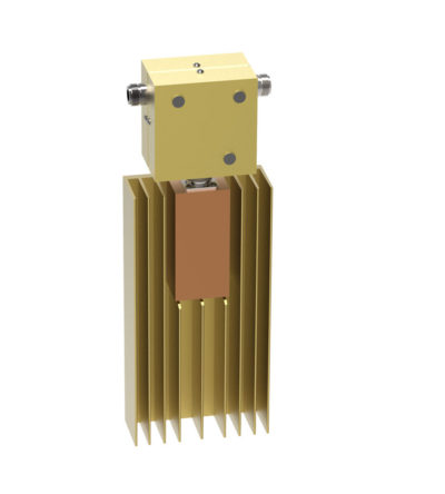
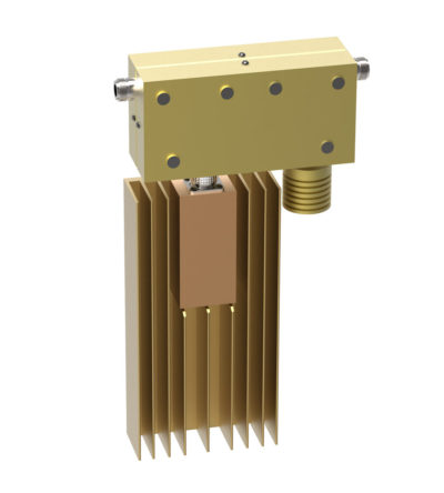
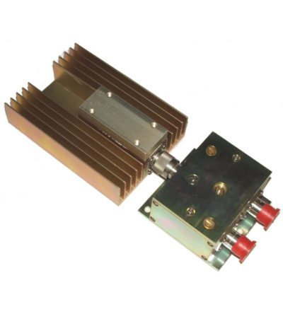
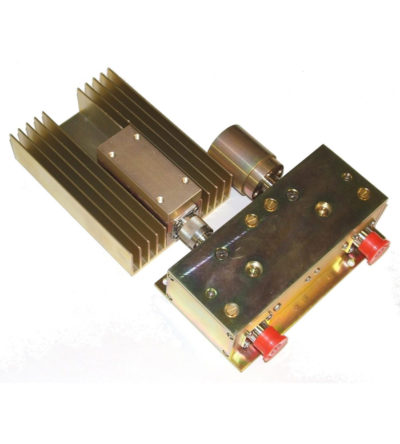
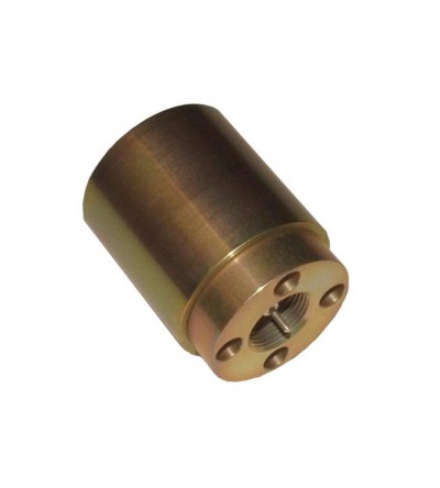
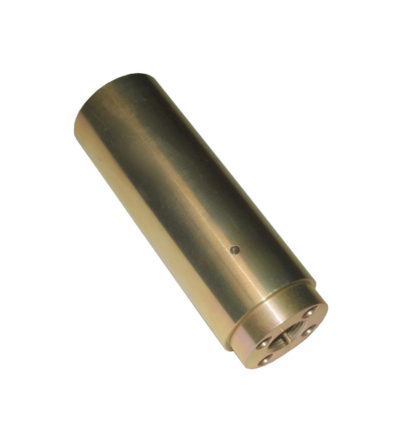
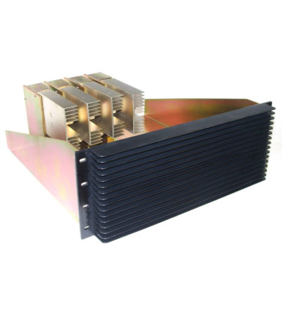
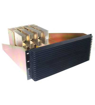
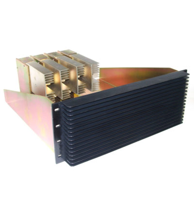
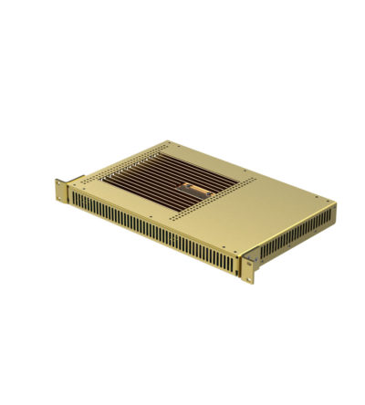
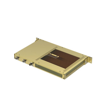
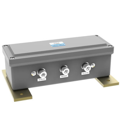
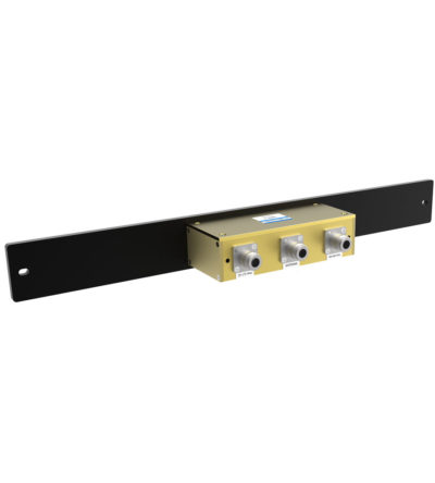
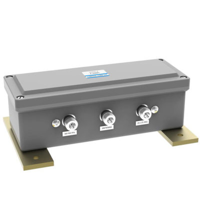
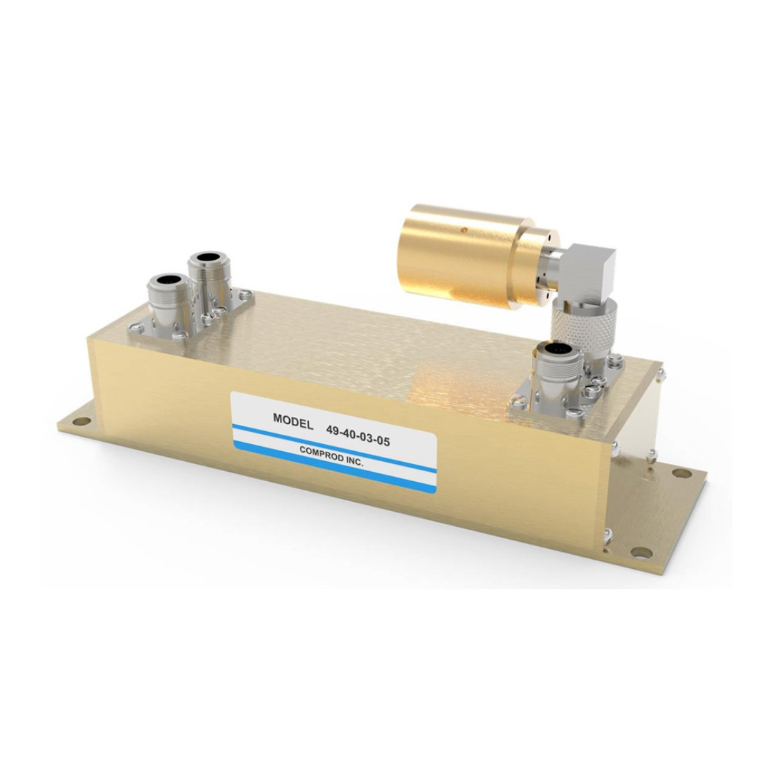
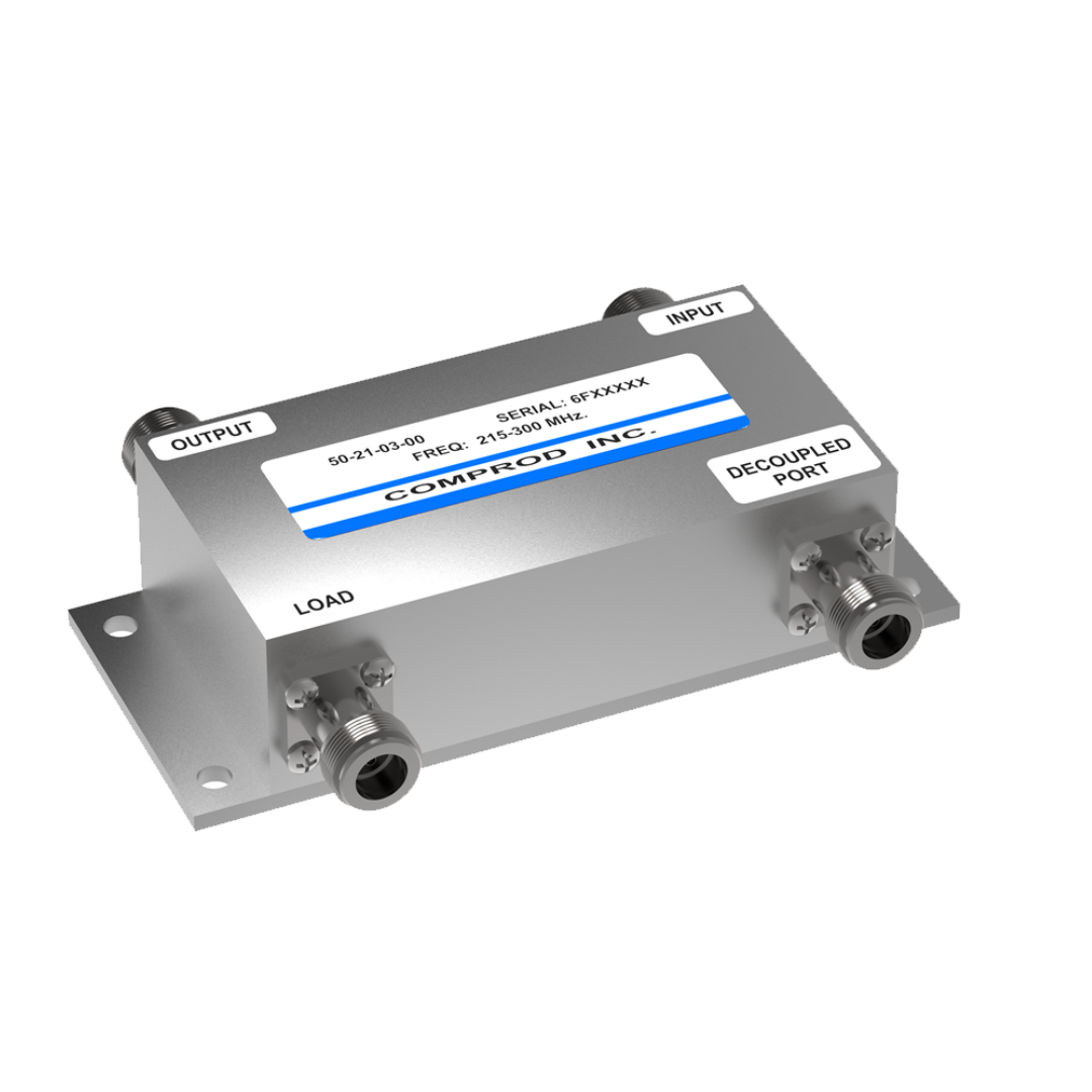
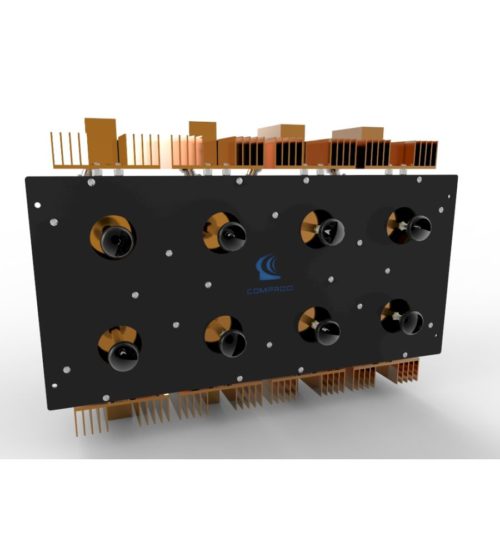
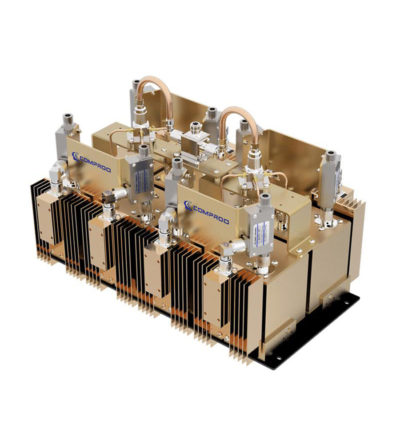
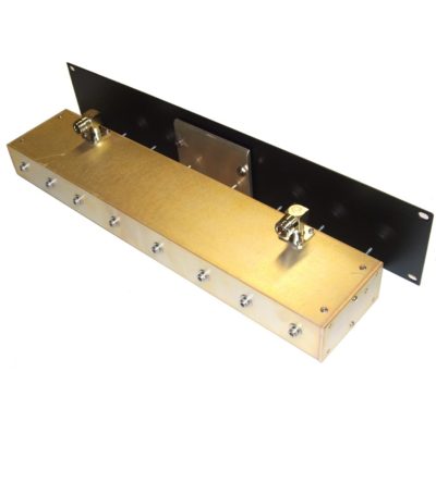
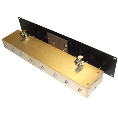
- Used for intermodulation panels, protecting your transmitters from reflected power and providing extra isolation
- High isolation: minimizes intermodulation products
- Low loss: maximizes system performance
- Continuous power: physical size and materials used maximize the performance across the operating band
- Can be combined with a variety of loads, 5/25/60/100/150/250 watt combinations, as well as with second harmonic filters for Hybrid Combiners (HTCs )
-
 Ideal for blocking the transfer of RF power flow in the opposite direction
 -
 Ideal for blocking the transfer of RF power flow in the opposite direction
- Used for intermodulation panels, protecting your transmitters from reflected power and providing extra isolation
- High isolation: minimizes intermodulation products
- Low loss: maximizes system performance
- Continuous power: physical size and materials used maximize the performance across the operating band
- Can be combined with a variety of loads, 5/25/60/100/150/250 watt combinations, as well as with second harmonic filters for Hybrid Combiners (HTCs )
-
 Ideal for blocking the transfer of RF power flow in the opposite direction
- Used for intermodulation panels, protecting your transmitters from reflected power and providing extra isolation
- High isolation: minimizes intermodulation products
- Low loss: maximizes system performance
- Continuous power: physical size and materials used maximize the performance across the operating band
- Can be combined with a variety of loads, 5/25/60/100/150/250 watt combinations, as well as with second harmonic filters for Hybrid Combiners (HTCs )
-
 Ideal for blocking the transfer of RF power flow in the opposite direction
- Used for intermodulation panels, protecting your transmitters from reflected power and providing extra isolation
- High isolation: minimizes intermodulation products
- Low loss: maximizes system performance
- Continuous power: physical size and materials used maximize the performance across the operating band
- Can be combined with a variety of loads, 5/25/60/100/150/250 watt combinations, as well as with second harmonic filters for Hybrid Combiners (HTCs )
-
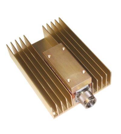
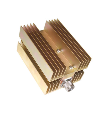
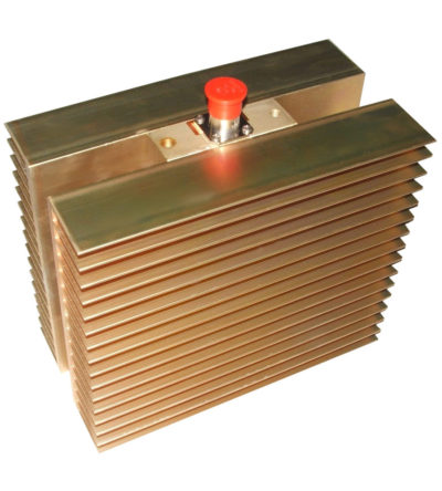
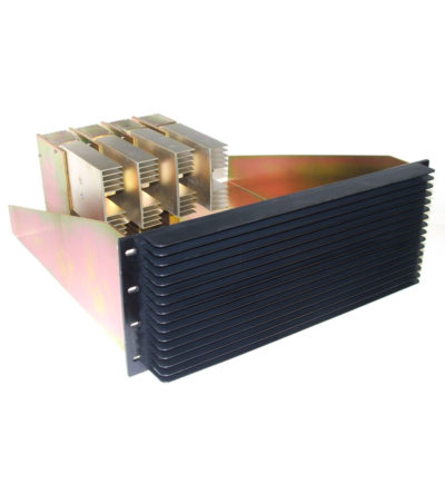
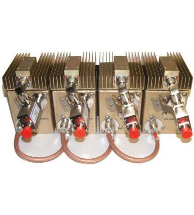
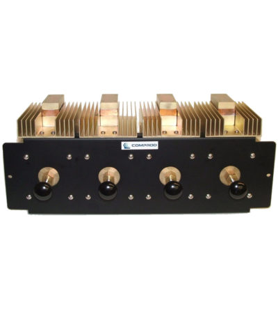
 Specifically designed to continually absorb reflected power
- Excellent return loss
- Oversized heat sinks
- Continuous duty power:
- 24/7 operation
- Install-and-forget
-
 Specifically designed to continually absorb reflected power
- Excellent return loss
- Oversized heat sinks
- Continuous duty power:
- 24/7 operation
- Install-and-forget
-
 Specifically designed to continually absorb reflected power
- Excellent return loss
- Oversized heat sinks
- Continuous duty power:
- 24/7 operation
- Install-and-forget
-
 Specifically designed to continually absorb reflected power
- Excellent return loss
- Oversized heat sinks
- Continuous duty power:
- 24/7 operation
- Install-and-forget
-
 Specifically designed to continually absorb reflected power
- Excellent return loss
- Oversized heat sinks
- Continuous duty power:
- 24/7 operation
- Install-and-forget
-
 Designed for compact, close frequency installations. Ideal for very closely spaced frequency transmitters
- Ideal for intermodulation panels, providing extra protection with their second harmonic filters, when physical space is at a premium or is constrained, and for providing extra isolation between two very close transmitters
- High isolation: minimizes intermodulation products
- Low loss: maximizes system performance
- Continuous power:
- Physical size and materials used maximizes the performance across the operating band
-
 Designed for compact, close frequency installations. Ideal for very closely spaced frequency transmitters
- Ideal for intermodulation panels, providing extra protection with their second harmonic filters, when physical space is at a premium or is constrained, and for providing extra isolation between two very close transmitters
- High isolation: minimizes intermodulation products
- Low loss: maximizes system performance
- Continuous power:
- Physical size and materials used maximizes the performance across the operating band
-
 Designed for compact, close frequency installations. Ideal for very closely spaced frequency transmitters
- Ideal for intermodulation panels, providing extra protection with their second harmonic filters, when physical space is at a premium or is constrained, and for providing extra isolation between two very close transmitters
- High isolation: minimizes intermodulation products
- Low loss: maximizes system performance
- Continuous power:
- Physical size and materials used maximizes the performance across the operating band
-
 Designed for compact, close frequency installations. Ideal for very closely spaced frequency transmitters
- Ideal for intermodulation panels, providing extra protection with their second harmonic filters, when physical space is at a premium or is constrained, and for providing extra isolation between two very close transmitters
- High isolation: minimizes intermodulation products
- Low loss: maximizes system performance
- Continuous power:
- Physical size and materials used maximizes the performance across the operating band
-

 Designed for compact, close frequency installations. Ideal for very closely spaced frequency transmitters
- High isolation: minimizes intermodulation products
- Low loss: maximizes system performance
- Continuous power:
- Physical size and materials used maximizes the performance across the operating band
-

 Designed for easy installation, reducing coaxial runs, and in-building applications with multi-band antennas
- Allows multiple bands to share the same transmission lines
- Available in VHF, UHF and 800/900 MHz bands
- Can be Tower-Mounted (TM), Rack-Mounted (RM) or stand alone
-

 Designed for easy installation, reducing coaxial runs, and in-building applications with multi-band antennas
- Allows multiple bands to share the same transmission lines
- Available in VHF, UHF and 800/900 MHz bands
- Can be Tower-Mounted (TM), Rack-Mounted (RM) or stand alone
-
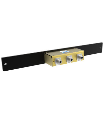
 Bi-directional coupler, ideally suited for two-way communications systems
- Low insertion loss
- High isolation between ports
- Excellent VSWR
- Tri-band and other models are available and customizable.
-
 Multilayer bonded PCB for high performance and compact design
- Low insertion loss
- Excellent return loss
- Compact dimensions saving space
- 3, 4.8, 6, 7, 10, 15, 20 and 30 dB values
- 200 Watts maximum main line power
- Integrated mounting bracket
-
 Multilayer bonded PCB for high performance and compact design
- Low insertion loss
- Excellent return loss
- Compact dimensions saving space
- 3, 4.8, 6, 7, 10, 15, 20 and 30 dB values
- 200 Watts maximum main line power
- Integrated mounting bracket
-

 Dielectric resonator technology resulting in higher performance than standard RF cavities in a much smaller package
- Available for the 764-776, 851-869 and 935-941 MHz bands
- Designed for tight channel spacing
- Lowest insertion loss, high isolation for maximum coverage and reduced interference
- Easy field expandability with X-Pass technology - one channel at a time
- Compact, robust design for rapid installations, increased mobility and ease of maintenance
-

 Dielectric resonator technology resulting in higher performance than standard RF cavities in a much smaller package
- Available for the 764-776, 851-869 and 935-941 MHz bands
- Designed for tight channel spacing
- Lowest insertion loss, high isolation for maximum coverage and reduced interference
- Star configuration
- Compact, robust design for rapid installations, increased mobility and ease of maintenance
-
 Designed for minimizing interference from adjacent channels and outside systems
- Temperature-compensated to ensure frequency stability
- High attenuation to minimize desense and interference from adjacent systems
- Silver-plated loops and tuning rods
-
 Designed for minimizing interference from adjacent channels and outside systems
- Temperature-compensated to ensure frequency stability
- High attenuation to minimize desense and interference from adjacent systems
- Silver-plated loops and tuning rods
-
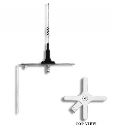
 High quality, high performance, utility-grade antenna
- Custom-designed
- Meets your specific needs
- Designed for any application as required by the customer
- Please contact a technical support technician for consultation.
-
 Designed for minimizing interference from adjacent channels and outside systems
- Temperature-compensated to ensure frequency stability
- High attenuation to minimize desense and interference from adjacent systems
- Silver-plated loops and tuning rods
-
 Designed for minimizing interference from adjacent channels and outside systems
- Temperature-compensated to ensure frequency stability
- High attenuation to minimize desense and interference from adjacent systems
- Silver-plated loops and tuning rods

