- Custom-designed
- Meets your specific needs
- Designed for any application as required by the customer
- Please contact a technical support technician for consultation.
-
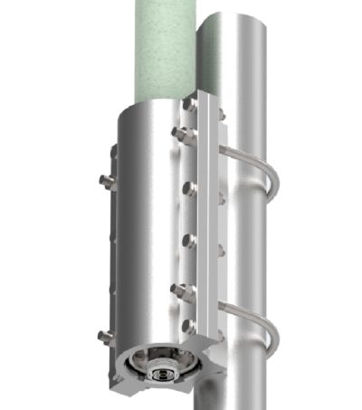
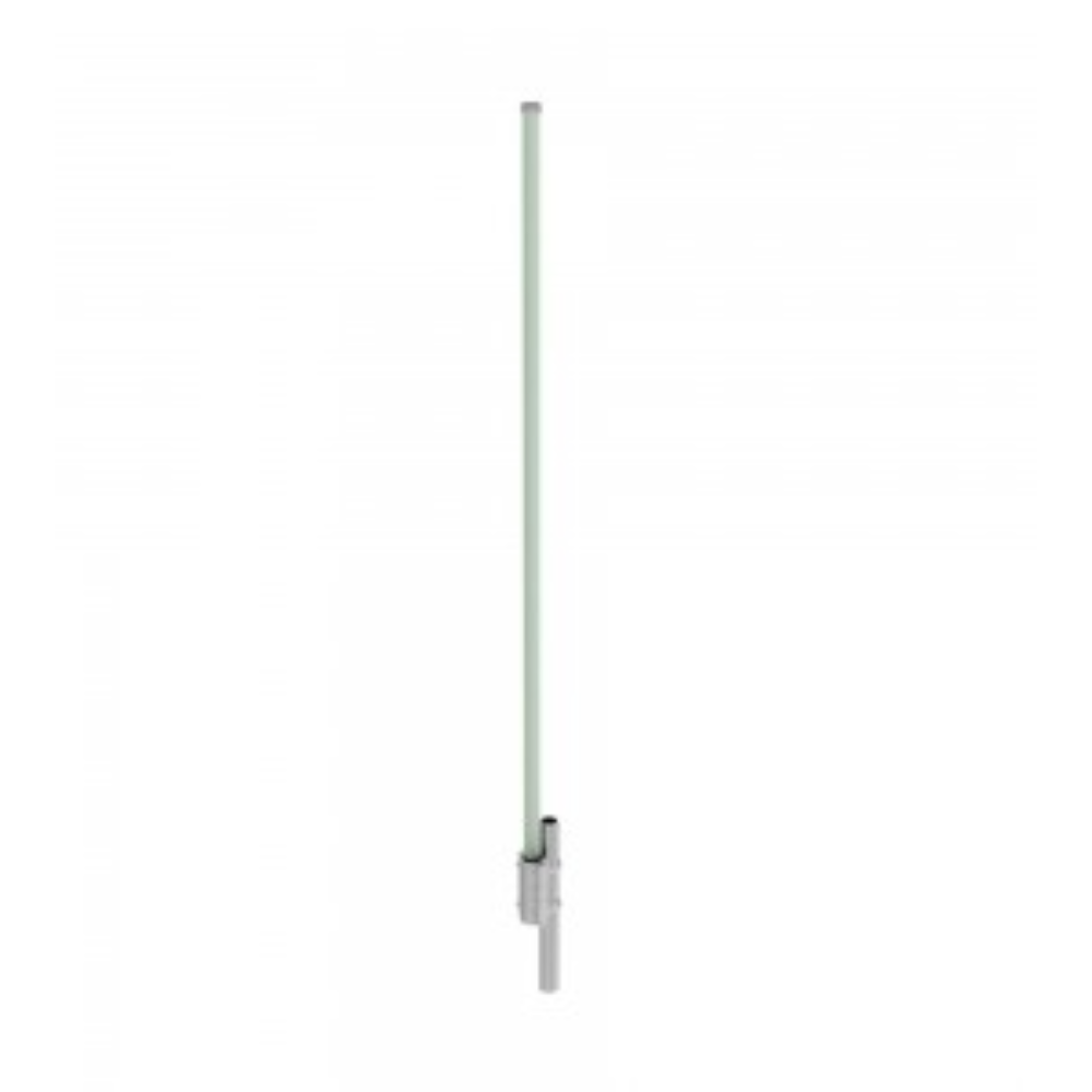
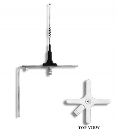
 High quality, high performance, utility-grade antenna
 -
Available in three frequency splits: 746-806; 806-869 or 885-960 within the 746 to 960 MHz range.
- Constructed with a high quality fiberglass light-grey radome
- Aluminum mounting hardware included with the antenna
-
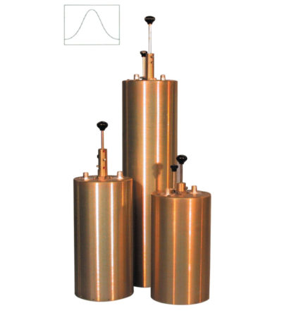
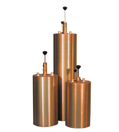
Designed to minimize interference from adjacent channels and outside systems
- Available in single, dual or triple units
- Temperature compensated to ensure frequency stability
- High attenuation
- Adjustable loops: each cavity has a calibration index to reference insertion loss
-
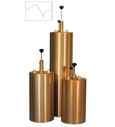
Designed to pass a frequency band and reject a narrow band of frequencies
- Can reject frequencies on either the high or low side of the pass frequency
- Temperature compensated to ensure frequency stability
- High attenuation to minimize desense and interference
-
Ideal for high power, close frequency separation installations
- Designed for combining two frequencies that require extra isolation. Can also be used as efficient pre-selectors
- Temperature compensated to ensure frequency stability
- High attenuation to minimize desense and interference from adjacent systems
- Adjustable loops
-
Designed for flexible, close frequency systems
- Each cavity has both a Reject and a Pass band curve
- Available in single units, they can be combined with band pass, notch, and pass reject cavities for added protection and isolation
- Temperature compensated to ensure frequency stability
- High attenuation to minimize desense and interference from adjacent systems
- Adjustable loops: each cavity has a calibration index for easy field tuning
-
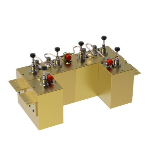
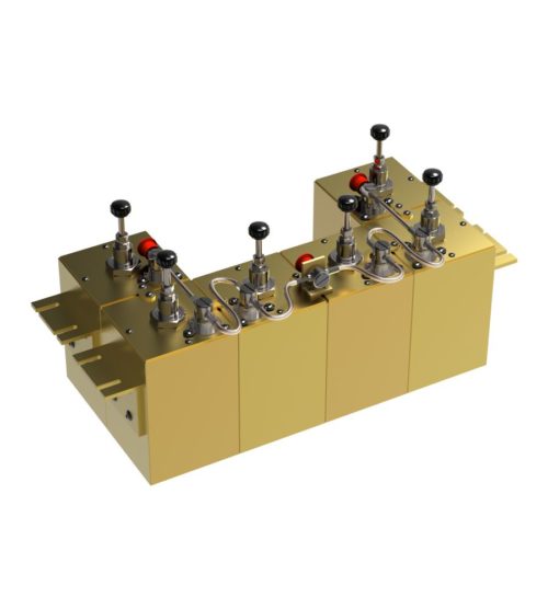
Incorporates expandability, close frequency spacing and some of the lowest insertion losses in the industry
- Can easily support 250 kHz Tx-Tx spacing
- Flexible design: from 1-21 channel capacity
- Expandable: 1 or more additional channels at a time; re-configurable equipment
- 746-1000 MHz, 254 MHz of operating bandwidth
- Temperature compensation to ensure frequency stability
- High attenuation to minimize desense and interference
- Ultra-low insertion losses; low coupling and bridging losses
- Continuous high-power handling capability; 150 watts – 24/7
-
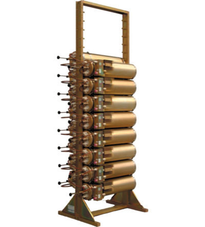
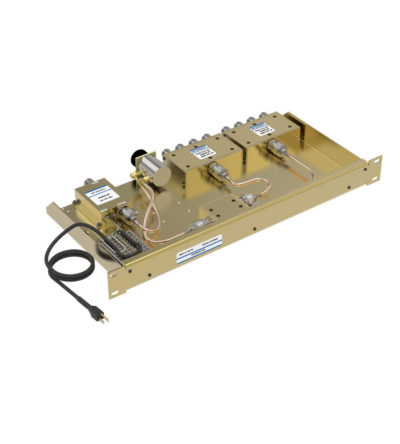
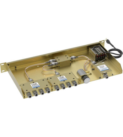
Ideal for combining multiple Rx frequencies onto the same antenna
- Available in 2, 4, 8, 12, 16 and 32
- Simple and cost-effective design
- Standard 19” Rack Mount (RM) or cavity-mounted (CM) versions
- Each unit consists of a power splitter and an RF amplifier.
- Plug-in Power Supply (PS) optional
-
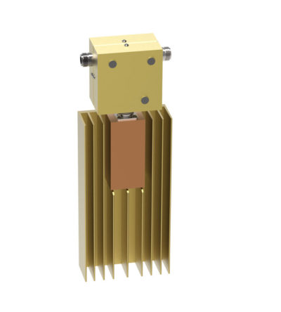
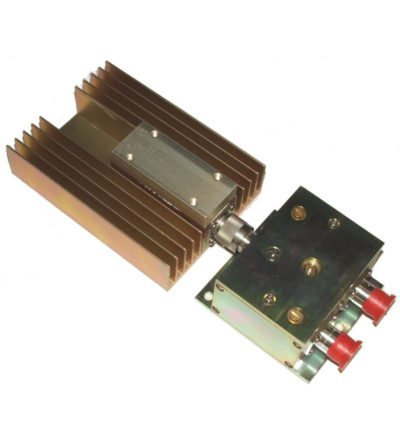
Ideal for blocking the transfer of RF power flow in the opposite direction
- Used for intermodulation panels, protecting your transmitters from reflected power and providing extra isolation
- High isolation: minimizes intermodulation products
- Low loss: maximizes system performance
- Continuous power: physical size and materials used maximize the performance across the operating band
- Can be combined with a variety of loads, 5/25/60/100/150/250 watt combinations, as well as with second harmonic filters for Hybrid Combiners (HTCs )
-
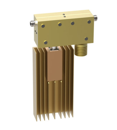
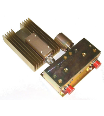
Ideal for blocking the transfer of RF power flow in the opposite direction
- Used for intermodulation panels, protecting your transmitters from reflected power and providing extra isolation
- High isolation: minimizes intermodulation products
- Low loss: maximizes system performance
- Continuous power: physical size and materials used maximize the performance across the operating band
- Can be combined with a variety of loads, 5/25/60/100/150/250 watt combinations, as well as with second harmonic filters for Hybrid Combiners (HTCs )
-
Ideal for blocking the transfer of RF power flow in the opposite direction
- Used for intermodulation panels, protecting your transmitters from reflected power and providing extra isolation
- High isolation: minimizes intermodulation products
- Low loss: maximizes system performance
- Continuous power: physical size and materials used maximize the performance across the operating band
- Can be combined with a variety of loads, 5/25/60/100/150/250 watt combinations, as well as with second harmonic filters for Hybrid Combiners (HTCs )