- Low insertion loss
- Excellent return loss
- Compact dimensions saving space
- 3, 4.8, 6, 7, 10, 15, 20 and 30 dB values
- 200 Watts maximum main line power
- Integrated mounting bracket
-
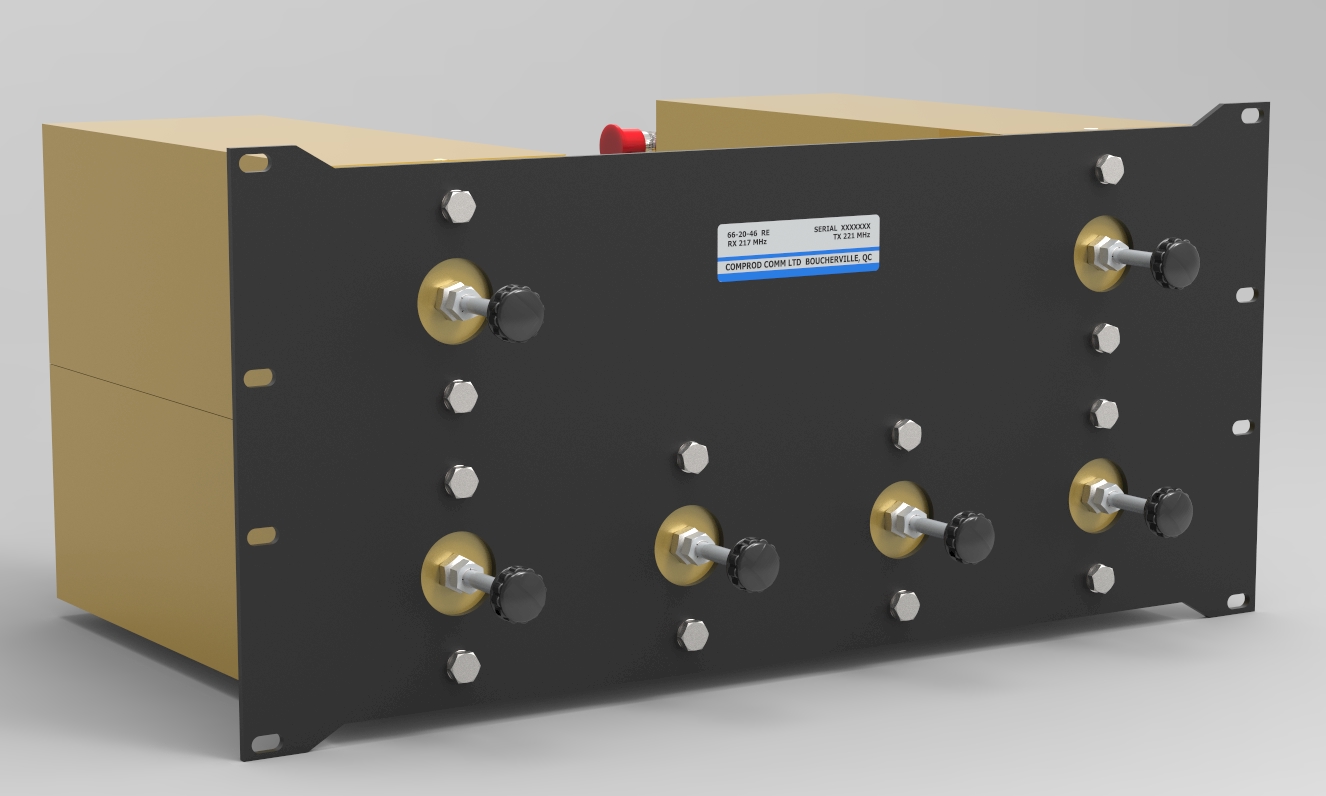
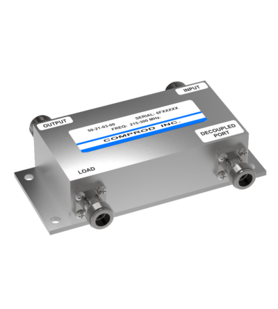
 Multilayer bonded PCB for high performance and compact design
 -
Designed for compact, close frequency installations. Ideal for very closely spaced frequency transmitters
- Ideal for intermodulation panels, providing extra protection with their second harmonic filters, when physical space is at a premium or is constrained, and for providing extra isolation between two very close transmitters
- High isolation: minimizes intermodulation products
- Low loss: maximizes system performance
- Continuous power:
- Physical size and materials used maximizes the performance across the operating band
-
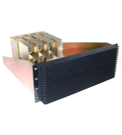
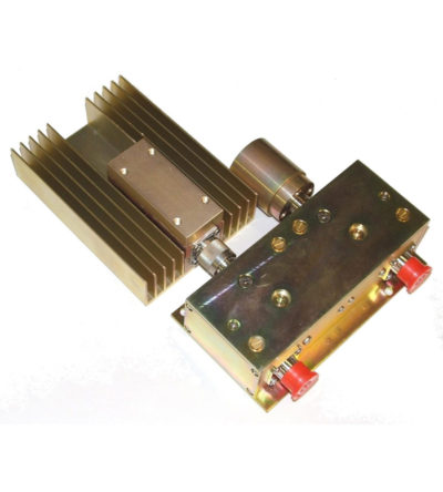
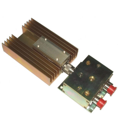
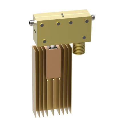
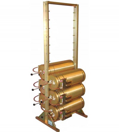
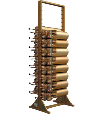
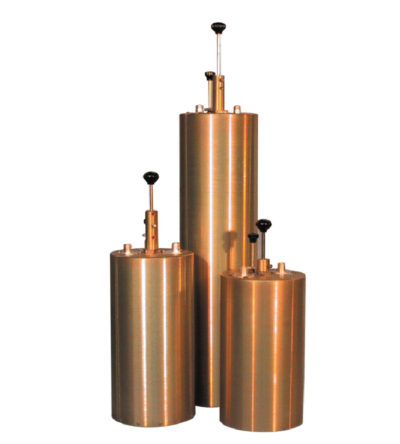
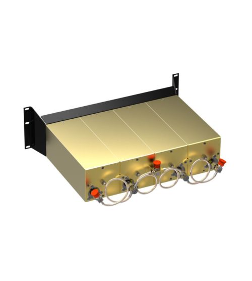
Specifically designed to continually absorb reflected power
- Excellent return loss
- Oversized heat sinks
- Continuous duty power:
- 24/7 operation
- Install-and-forget
-
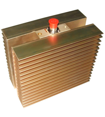
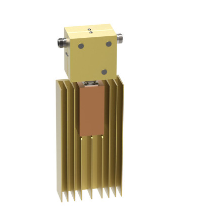
Specifically designed to continually absorb reflected power
- Excellent return loss
- Oversized heat sinks
- Continuous duty power:
- 24/7 operation
- Install-and-forget
-
Specifically designed to continually absorb reflected power
- Excellent return loss
- Oversized heat sinks
- Continuous duty power:
- 24/7 operation
- Install-and-forget
-
Specifically designed to continually absorb reflected power
- Excellent return loss
- Oversized heat sinks
- Continuous duty power:
- 24/7 operation
- Install-and-forget
-
Specifically designed to continually absorb reflected power
- Excellent return loss
- Oversized heat sinks
- Continuous duty power:
- 24/7 operation
- Install-and-forget
-
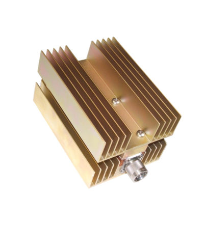
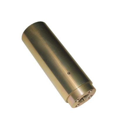
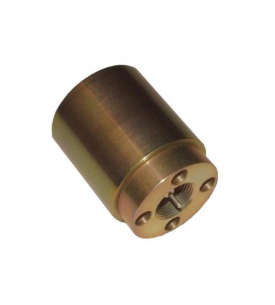
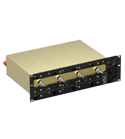
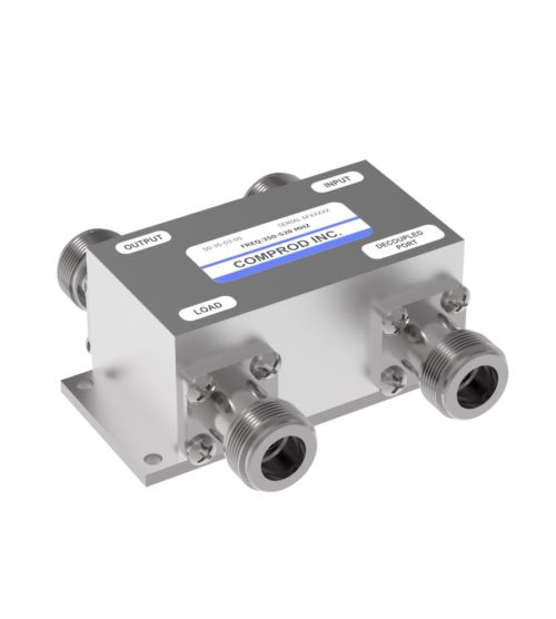
Ideal for blocking the transfer of RF power flow in the opposite direction
- Used for intermodulation panels, protecting your transmitters from reflected power and providing extra isolation
- High isolation: minimizes intermodulation products
- Low loss: maximizes system performance
- Continuous power: physical size and materials used maximize the performance across the operating band
- Can be combined with a variety of loads, 5/25/60/100/150/250 watt combinations, as well as with second harmonic filters for Hybrid Combiners (HTCs )
-
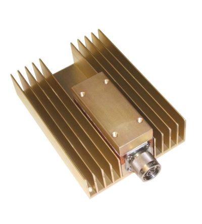
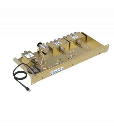
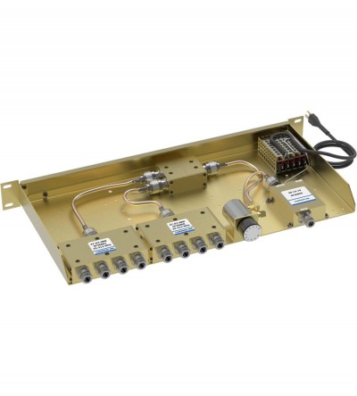
Ideal for combining multiple Rx frequencies onto the same antenna
- Available in 2, 4, 8, 12, 16 and 32 port configurations
- Simple and cost-effective design
- Standard 19” Rack Mount (RM) or cavity-mounted (CM) versions
- Each unit consists of a power splitter and an RF amplifier.
- Plug-in Power Supply (PS) optional
-
Incorporates expandability, close frequency spacing and some of the lowest insertion losses in the industry
- Can easily support 75 kHz Tx-Tx spacing or 50 kHz spacing while using 10” cavities
- Flexible design: from 1-21 channel capacity
- Expandable: 1 or more additional channels at a time; re-configurable equipment
- 132-174 MHz, 42 MHz of operating bandwidth
- Temperature compensation to ensure frequency stability
- High attenuation to minimize desense and interference
- Ultra-low insertion losses; low coupling and bridging losses
- Continuous high-power handling capability; 150 watts – 24/7
-
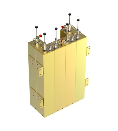
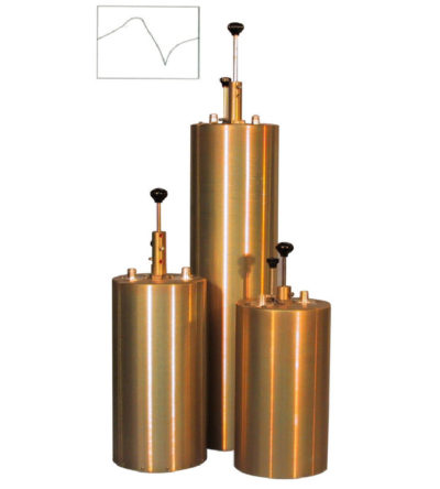
Designed for flexible, close frequency systems
- Each cavity has both a Reject and a Pass band curve
- Available in single units, they can be combined with band pass, notch, and pass reject cavities for added protection and isolation
- Temperature compensated to ensure frequency stability
- High attenuation to minimize desense and interference from adjacent systems
- Adjustable loops: each cavity has a calibration index for easy field tuning
-
Individually calibrated to ensure the best performance in a disguised appearance
- Two or three separate frequency segments in a given mobile band
- Cross-channel operation in two mobile bands with one antenna
- Alternative antennas to an OEM version will be recommended, where required (e.g. Euro-style, or universal mount traditional whip)
-
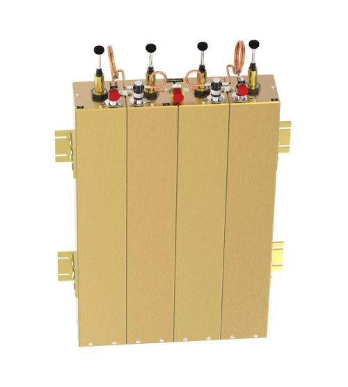
Designed for flexible, close frequency systems
- Each cavity has both a Reject and a Pass band curve
- Available in single units, they can be combined with band pass, notch, and pass reject cavities for added protection and isolation
- Temperature compensated to ensure frequency stability
- High attenuation to minimize desense and interference from adjacent systems
- Adjustable loops: each cavity has a calibration index for easy field tuning
-
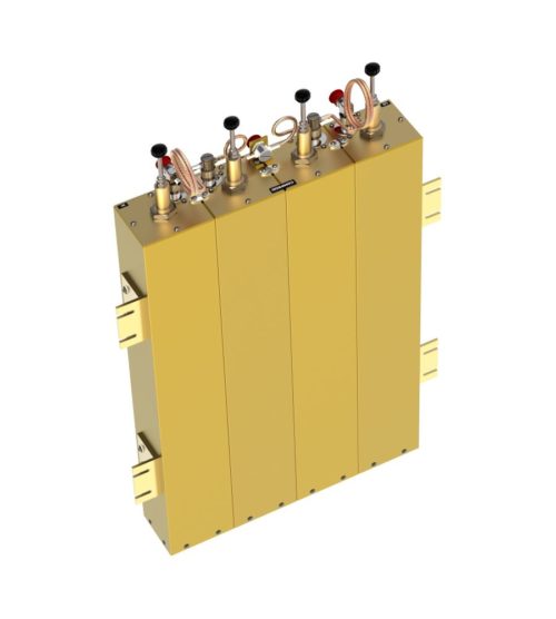
Features compact size, low loss and temperature compensation over the range of -40ºC to +60ºC
- Extruded aluminum cavities and solid- shield copper-jacketed inter-cabling that ensures excellent mechanical and electrical stability
- All units are adjustable in the field and rated at 50 watts continuous duty with a maximum VSWR of 1.5: 1 over the entire tuning range.
- BNC connectors are standard.
-
Features compact size, low loss and temperature compensation over the range of -40ºC to +60ºC
- Extruded aluminum cavities and solid- shield copper-jacketed inter-cabling that ensures excellent mechanical and electrical stability
- All units are adjustable in the field and rated at 50 Watts maximum with a maximum VSWR of 1.5: 1 over the entire tuning range.
- BNC connectors are standard.
-
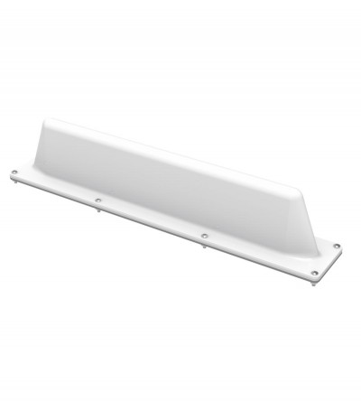
Ideal for low clearance applications such as those found on trains, public transit vehicles, construction equipment and police vehicles
- Low-profile rugged alternative to a ¼-wave whip mobile antenna
- When mounted on a horizontal surface, maximum radiation is omnidirectional and vertically polarized
- Impact-resistant ABS radome
- Supplied with a mounting gasket to ensure a moisture-proof installation
-
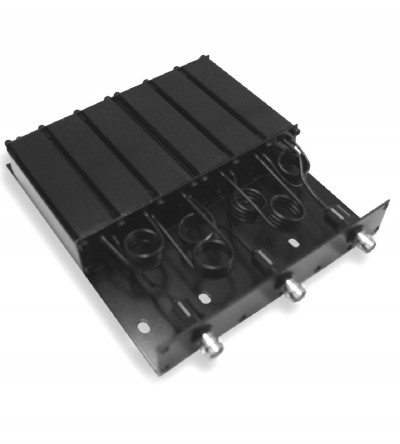
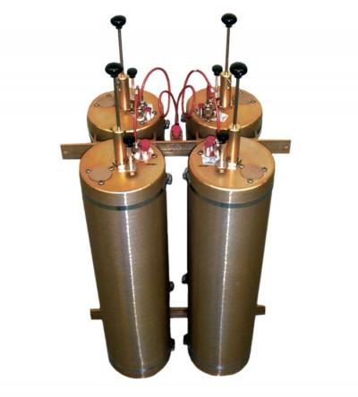
Ideal for high power, close frequency separation installations
- Designed for combining two frequencies that require extra isolation. Can also be used as efficient pre-selectors
- Temperature compensated to ensure frequency stability
- High attenuation to minimize desense and interference from adjacent systems
- Adjustable loops
-
Ideal for low clearance applications such as those found on trains, public transit vehicles, construction equipment and police vehicles
- Low-profile rugged alternative to a ¼-wave whip mobile antenna
- When mounted on a horizontal surface, maximum radiation is omnidirectional and vertically polarized
- High strength cast aluminum design. Can be coated for additional protection against harsh environmental conditions
- Supplied with an O-ring to ensure a moisture-proof installation
-
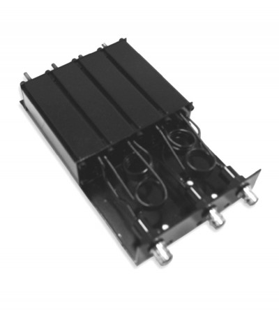
Ideal for high power, close frequency separation installations
- Designed for combining two frequencies that require extra isolation. Can also be used as efficient pre-selectors
- Temperature compensated to ensure frequency stability
- High attenuation to minimize desense and interference from adjacent systems
- Adjustable loops
-
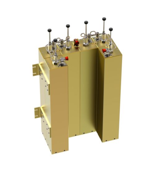
Ideal for compact high performance applications
- Designed for the combination of two frequencies that require extra isolation. Can also be used as efficient pre-selectors
- An eight cavity configuration is also available for a higher level of isolation and selectivity
- Can be retuned in the field
-
Ideal for compact high performance applications
- Designed for the combination of two frequencies that require extra isolation. Can also be used as efficient pre-selectors
- A six and an eight cavity configuration is also available for a higher level of isolation and selectivity
- Can be retuned in the field
-
Designed for quick and easy installations
- Designed for the combination of two frequencies requiring extra isolation. Can also be used as efficient pre-selectors
- Available in 4 or 6 cavity configurations
- Temperature compensated to ensure frequency stability
- High attenuation to minimize desense and interference from adjacent systems
- Adjustable loops: each cavity has a calibration index for easy field tuning
-
Designed to reject one narrow band of frequencies, while letting all others pass in the operating band
- Can be cascaded or added to one another in order to sharpen the attenuation of the rejection curve
- Temperature compensated to ensure frequency stability
- High attenuation to minimize desense and interference from adjacent systems
- Adjustable loops: each cavity has a calibration index
-
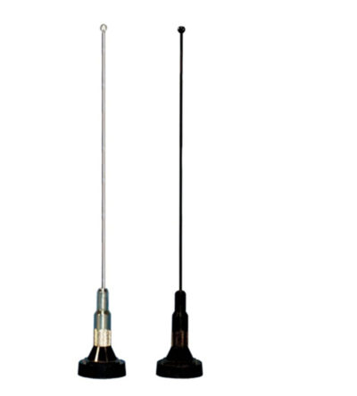
Unity gain in a wideband design for heavy-duty service
- Manufactured using the best corrosion-resistant materials and finishes available
- Ultrasonically-welded brass insert and a gold-plated spring-loaded contact
- Shipped with a 19” whip that can be cut by the customer to any frequency between 136 MHz and 960 MHz
- Standard Motorola NMO type mount providing an excellent moisture seal even when the antenna is removed
-
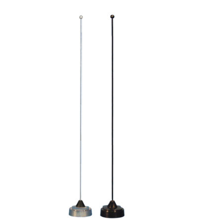
Unity gain in a wideband design for heavy-duty service
- Manufactured using the best corrosion-resistant materials and finishes available
- Ultrasonically-welded brass insert and a gold-plated spring-loaded contact
- Shipped with a factory tuned whip cut to size based on the customer specified frequency range between 136 MHz and 960 MHz
- Standard Motorola NMO type mount providing an excellent moisture seal even when the antenna is removed
-
Designed to pass a frequency band and reject a narrow band of frequencies
- Can reject frequencies on either the high or low side of the pass frequency
- Temperature compensated to ensure frequency stability
- High attenuation to minimize desense and interference