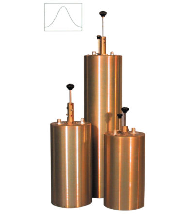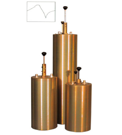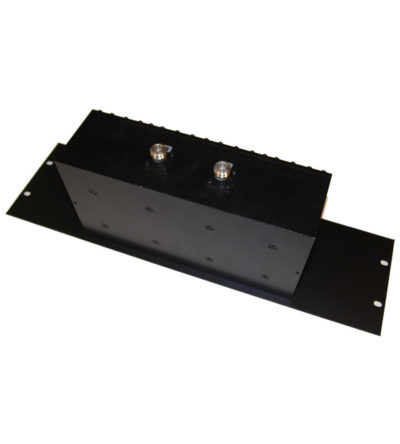
Designed for minimizing interference from adjacent channels and outside systems
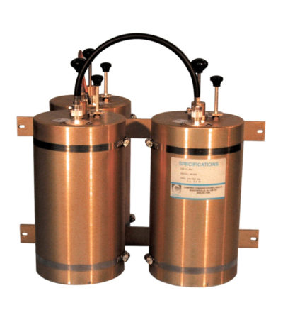
- Temperature-compensated to ensure frequency stability
- High attenuation to minimize desense and interference from adjacent systems
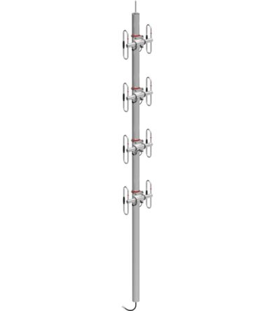
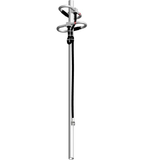
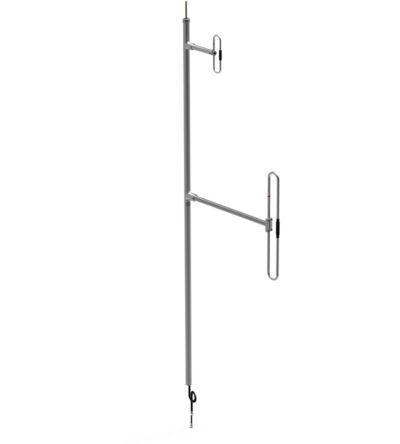
- Silver-plated loops and tuning rods