-
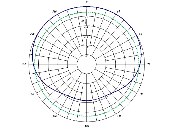
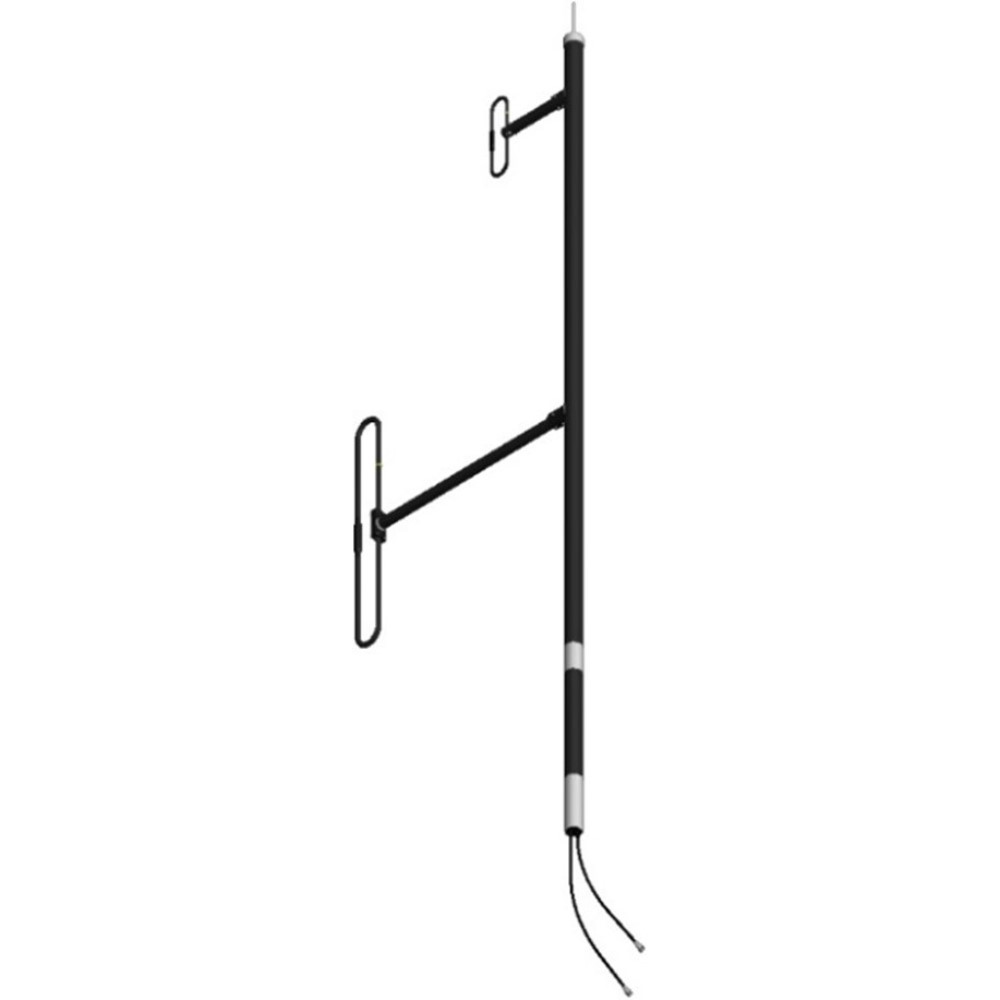
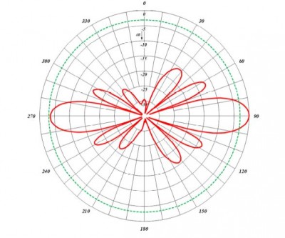
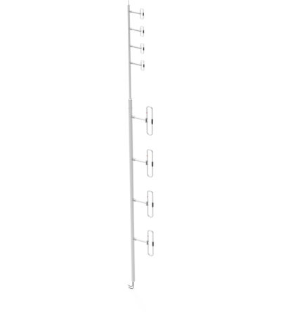
 The F-3647 is a wideband dual antenna with an 871F-70 on the base and a 771-70 on the top. The antenna offers for the 871F-70 & 771-70 a choice of radiation patterns that are determined by the dipole-to-mast spacing. The F-3647 has an internal cabling and is not field adjustable. The 871F-70 & 771-70 antenna is offered in a ¼, 3/8, or ½ wave pattern spacing versions. The antenna can be black anodized. Heavy Duty version of the antenna is also available. DOWNLOAD PDF DOWNLOAD DIGITAL PATTERNS
 -
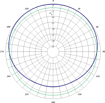
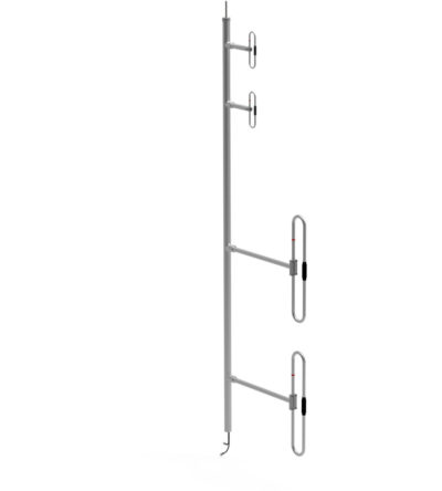
The F-3647 is a heavy duty wideband dual antenna with an 871F-70 on the base and a 771-70 on the top. The antenna offers for the 871F-70 & 771-70 a choice of radiation patterns that are determined by the dipole-to-mast spacing. The F-3647 has an internal cabling and is not field adjustable. The 871F-70 & 771-70 antenna is offered in a ¼, 3/8, or ½ wave pattern spacing versions. The antenna can be black anodized. Heavy Duty version of the antenna is also available. DOWNLOAD PDF DOWNLOAD DIGITAL PATTERNS
-
Ideal for applications where costs are calculated per antenna
- Available in many configurations
- VHF, UHF or 700/800/900 MHz antennas can be combined onto one mast
- Mix and match with our 770, 790 and 870 series antennas
- Can be configured for side or top mount
- Low VSWR version with maximum gain over the specified frequencies
- Heavy-duty versions available
-
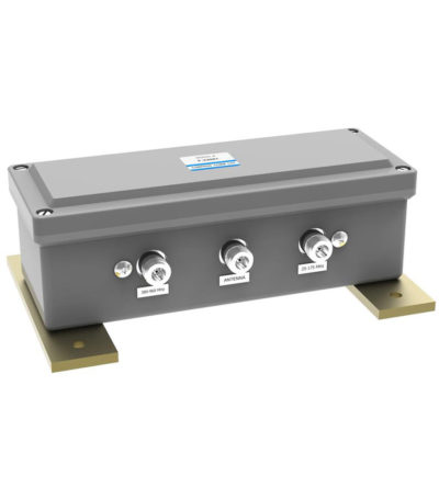
Designed for external Public Safety Radio Frequencies to propagate within buildings, tunnels or public use environments
- Multiple frequency bands
- Aluminum painted
-
Designed for external Public Safety Radio Frequencies to propagate within buildings, tunnels or public use environments
- Aluminium painted
-
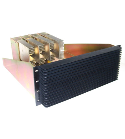
Designed for compact, close frequency installations. Ideal for very closely spaced frequency transmitters
- Ideal for intermodulation panels, providing extra protection with their second harmonic filters, when physical space is at a premium or is constrained, and for providing extra isolation between two very close transmitters
- High isolation: minimizes intermodulation products
- Low loss: maximizes system performance
- Continuous power:
- Physical size and materials used maximizes the performance across the operating band
-
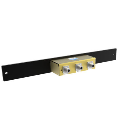
Designed for easy installation, reducing coaxial runs, and in-building applications with multi-band antennas
- Allows multiple bands to share the same transmission lines
- Available in VHF, UHF and 800/900 MHz bands
- Can be Tower-Mounted (TM), Rack-Mounted (RM) or stand alone
-
Designed for easy installation, reducing coaxial runs, and in-building applications with multi-band antennas
- Allows multiple bands to share the same transmission lines
- Available in VHF, UHF and 800/900 MHz bands
- Can be Tower-Mounted (TM), Rack-Mounted (RM) or stand alone