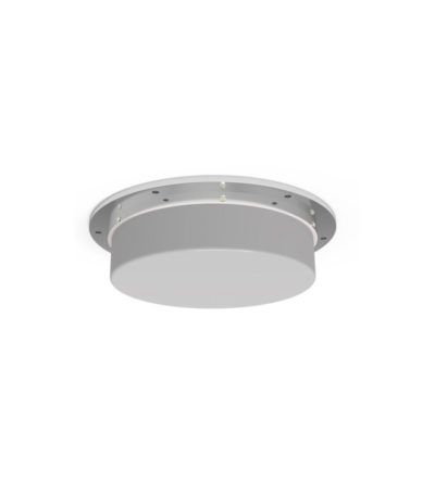
- Offered with Fire Retardant 6200 Kydex
- Meet the recommended fire safety practices of both the Federal Transit Administration (FTA) and the Federal Rail Administration (FRA) for smoke emission and flammability as tested under ASTM E-662 and ASTM E-162
-
 Designed for external Public Safety Radio Frequencies to propagate within buildings, tunnels or public use environments
 -
Designed for external Public Safety Radio Frequencies to propagate within buildings, tunnels or public use environmentsDOWNLOAD PDF DOWNLOAD DIGITAL PATTERNS
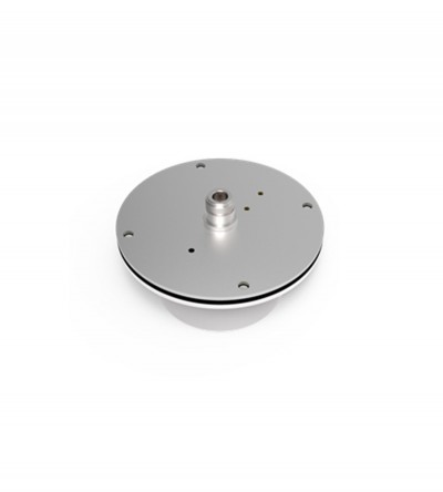
- Offered with Fire Retardant 6200 Kydex or ABS radomes
- Meet the recommended fire safety practices of both the Federal Transit Administration (FTA) and the Federal Rail Administration (FRA) for smoke emission and flammability as tested under ASTM E-662 and ASTM E-162
-
Designed for external Public Safety Radio Frequencies to propagate within buildings, tunnels or public use environmentsDOWNLOAD PDF INSTALLATION PDF DOWNLOAD DIGITAL PATTERNS
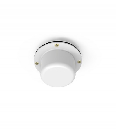
- Offered with Fire Retardant 6200 Kydex or ABS radomes
- Meet the recommended fire safety practices of both the Federal Transit Administration (FTA) and the Federal Rail Administration (FRA) for smoke emission and flammability as tested under ASTM E-662 and ASTM E-162
-
Designed for external Public Safety Radio Frequencies to propagate within buildings, tunnels or public use environments
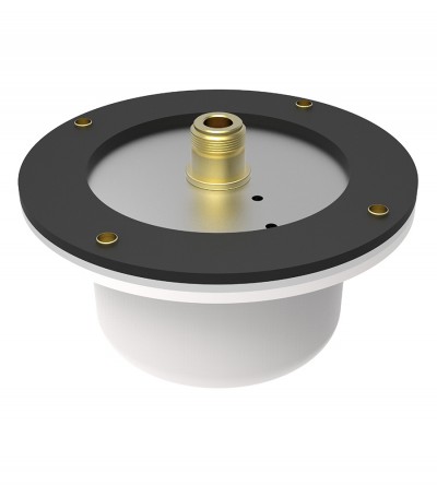
- Offered with Fire Retardant 6200 Kydex
- Meet the recommended fire safety practices of both the Federal Transit Administration (FTA) and the Federal Rail Administration (FRA) for smoke emission and flammability as tested under ASTM E-662 and ASTM E-162
-
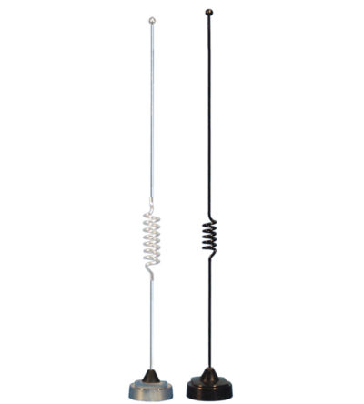
- 3.0 dBd gain achieved by featuring a 5/8-wave above a ¼ wave open coil design
- Manufactured using the best corrosion-resistant materials and finishes available
- Ultrasonically-welded brass insert and leaf spring-loaded contact for long-term reliability
- Standard NMO type mount providing an excellent moisture seal even when the antenna is removed
-
- 3.0 dBd gain achieved by featuring a 5/8-wave above a ¼ wave design
- Manufactured using the best corrosion-resistant materials and finishes available
- Ultrasonically-welded brass insert and leaf spring-loaded contact for long-term reliability
- Standard NMO type mount providing an excellent moisture seal even when the antenna is removed
-
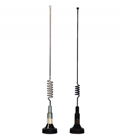
- 3.0 dBd gain achieved by featuring a 5/8-wave above a 1/2 wave closed coil design
- Manufactured using the best corrosion-resistant materials and finishes available
- Ultrasonically-welded brass insert and leaf spring-loaded contact for long-term reliability
- Standard NMO type mount providing an excellent moisture seal even when the antenna is removed
-
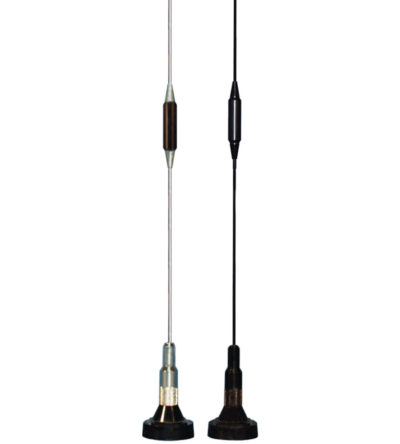
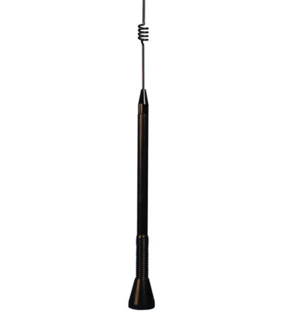
- 3.5 dBd gain achieved by featuring a 5/8-wave above a ¼ wave design
- Manufactured using the best corrosion-resistant materials and finishes available
- Features an integrated shock spring and a heavy-duty stainless steel whip that is designed to withstand severe shock
- Ultrasonically-welded brass insert and gold-plated, spring-loaded contact
- O-ring seals and overlap construction to ensure a moisture-proof installation
- Standard Motorola NMO type connector
-
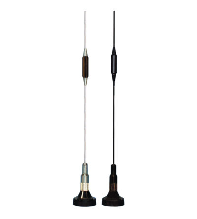
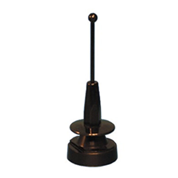
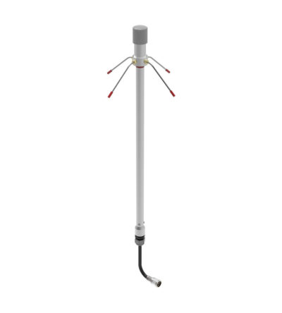
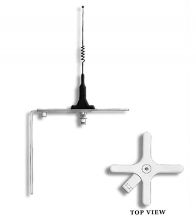
No ground plane antenna – Collinear design
- 3.0 dBd gain achieved by featuring a 5/8-wave above a ¼ wave design
- Elevated feed point that is ideal for the RF signal to clear any nearby obstructions
- Keeps the signals above and away from the passenger compartment
- Features a built-in shock spring and a spring-loaded contact for long-term dependability
- Standard NMO type mount providing an excellent moisture seal even when the antenna is removed
-
Perfect for both voice and data transmissions
- Very wide in bandwidth
- Low profile, extremely rugged and ideal for commercial applications
- Manufactured using the best corrosion-resistant materials and finishes available
- O-ring seals and overlap construction to ensure a moisture-proof installation
- Standard Motorola NMO type mount
-
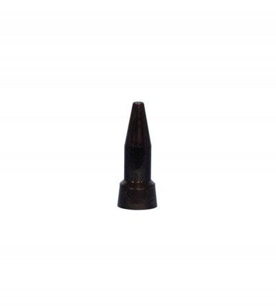
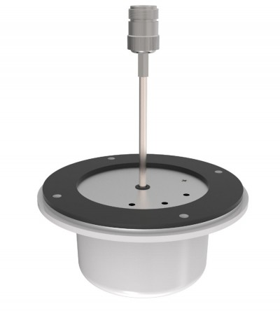
Ideal for low clearance applications such as those found on trains, mass transit vehicles, construction equipment and police and emergency vehicles
- Compact, low profile antennas in weatherproof ABS radomes
- When mounted on a horizontal surface, maximum radiation is omnidirectional and vertically polarized
- Space diversity design that provides greater communication reliability in a fading environment
- Supplied with an O-ring to ensure a moisture-proof installation
-
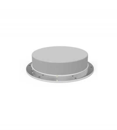
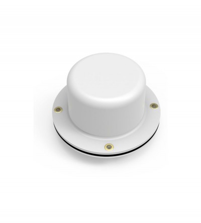
Ideal for low clearance applications such as those found on trains, mass transit vehicles, construction equipment and police and emergency vehicles
- When mounted on a horizontal surface, maximum radiation is omnidirectional and vertically polarized
- Standard, folded radiator housed in a sturdy high impact ABS radome
- Supplied with a mounting gasket to ensure a moisture-proof installation
-
Individually calibrated to ensure the best performance in a disguised appearance
- Two or three separate frequency segments in a given mobile band
- Cross-channel operation in two mobile bands with one antenna
- Alternative antennas to an OEM version will be recommended, where required (e.g. Euro-style, or universal mount traditional whip)
-
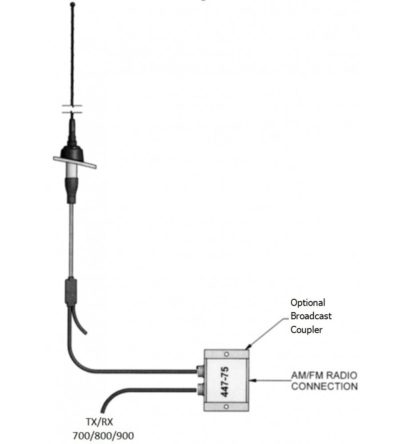
Very large bandwidth which make it ideal for emergency use or resale
- Available in 700/800/900 MHz configuration (2 frequency splits)
- Rugged design to withstand the most extreme environmental conditions
- The mounting hardware supplied will permit 0.75” to 2.3/8” O.D. pipe installation.
- DC ground for lightning protection
-
Ideal for trunking or cellular applications.
- This antenna is offered in an offset pattern, 1/2 wave versions.
- Each antenna is also available in an offset pattern, 1/4 wave versions.
- Broadband antennas are ideal for trunking or cellular applications.
- Weatherproof radome to ensure continuous service during severe environmental conditions.
- Versions with 3, 6, and 9-degree downtilt are also available.
-
Ideal for trunking or cellular applications
- This antenna is offered in an offset pattern, 1/4 wave versions.
- Each antenna is also available in an offset pattern, 1/2 wave versions.
- Broadband antennas are ideal for trunking or cellular applications.
- Weatherproof radome to ensure continuous service during severe environmental conditions.
- Versions with 3, 6, and 9-degree downtilt are also available.
-
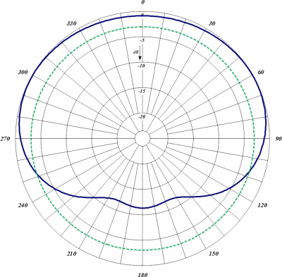
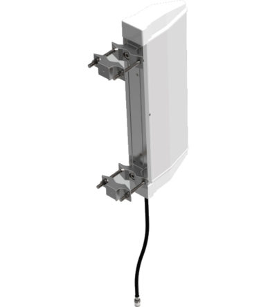
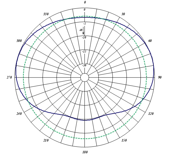
Ideal for trunking or cellular applications
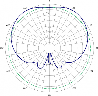
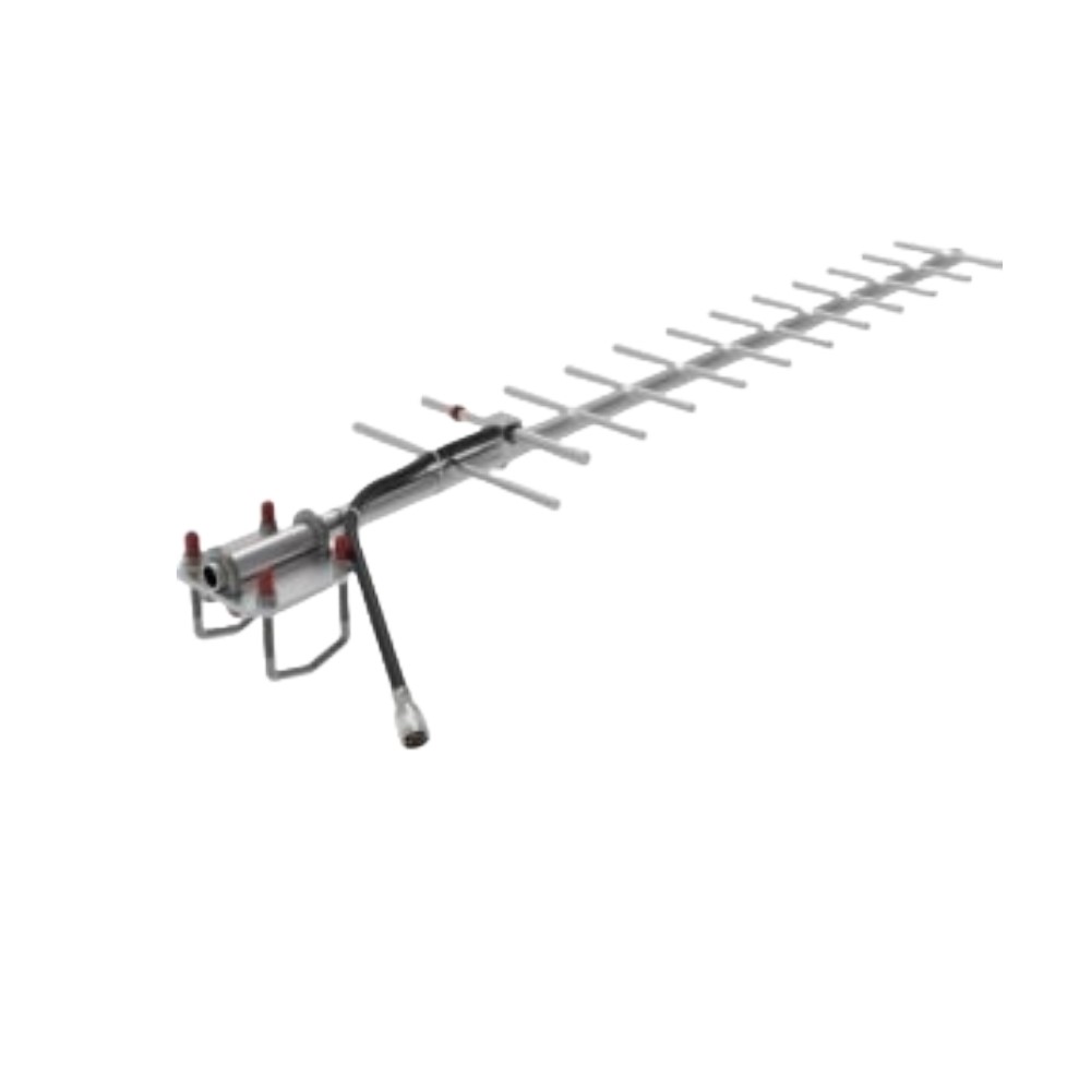
- Available in the 700/800/900 MHz configuration (2 frequency splits)
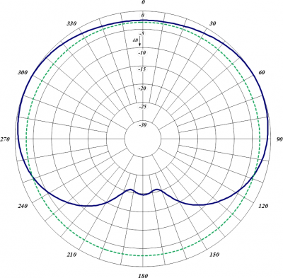
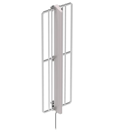
- These antennas have 1/4 wave spacing to the reflector.
- Reflector is field-adjustable and has 5 positions: 60º, 90º, 105º, 130º and 160º
- Weatherproof radome to ensure continuous service during severe environmental conditions
- Heavy-duty versions available
-
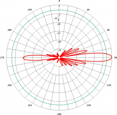
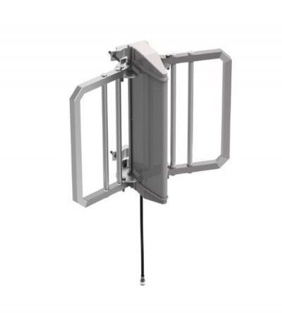
Ideal for trunking or cellular applications
- Available in the 700/800/900 MHz configuration (2 frequency splits)
- These antennas have 1/4 wave spacing to the reflector.
- Reflector is field-adjustable and has 5 positions: 60º, 90º, 105º, 130º and 160º
- Weatherproof radome to ensure continuous service during severe environmental conditions
- Heavy-duty versions available
-
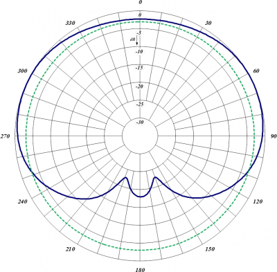
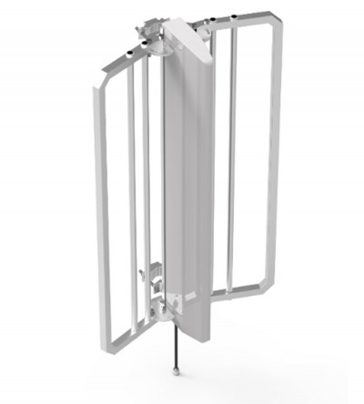
Ideal for trunking or cellular applicationsDOWNLOAD PDF DOWNLOAD DIGITAL PATTERNS
- Available in the 700/800/900 MHz configuration (2 frequency splits)
- These antennas have 1/4 wave spacing to the reflector.
- Reflector is field-adjustable and has 5 positions: 60º, 90º, 105º, 130º and 160º
- Weatherproof radome to ensure continuous service during severe environmental conditions
- Heavy-duty versions available
-
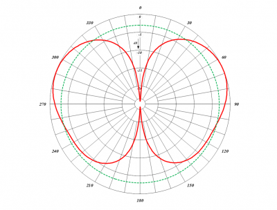
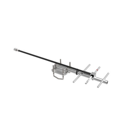
Rugged design to withstand harsh environmental conditions
- Available in the 700/800/900 MHz configuration (4 frequency splits)
- Vertical or horizontal polarization
- Fully welded for added durability
- Black anodized versions available
-
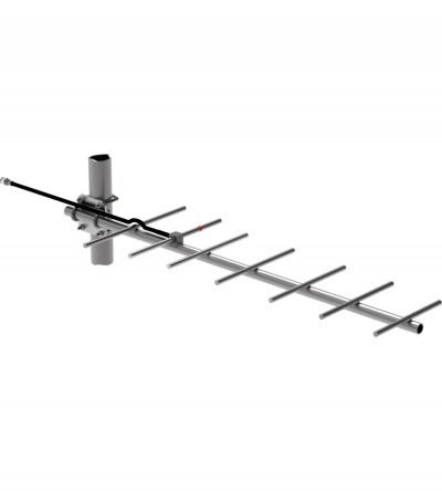
Rugged design to withstand harsh environmental conditions
- Available in the 700/800/900 MHz configuration (5 frequency splits)
- Vertical or horizontal polarization
- Fully welded for added durability
- Black anodized version available
- Mounting hardware (127-85) supplied
- 980-70*5 is our dual band 700/800 MHz antenna: 764-870 MHz
-
Rugged design to withstand harsh environmental conditions
- Available in the 700/800/900 MHz configuration (4 frequency splits)
- Vertical or horizontal polarization
- Fully welded for added durability
- Black anodized versions available
-
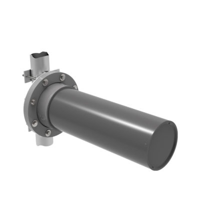
Heavy-duty versions, part of our “Avalanche Series"
- Rugged design to withstand harsh environmental conditions
- Available in UHF and 700/800/900 MHz configurations
- Vertical or horizontal polarization
- DC ground for lightning protection
- The PVC enclosure is ½ inch-thick water main.
-
High quality, high performance, utility-grade antenna
- Custom-designed
- Meets your specific needs
- Designed for any application as required by the customer
- Please contact a technical support technician for consultation.
-
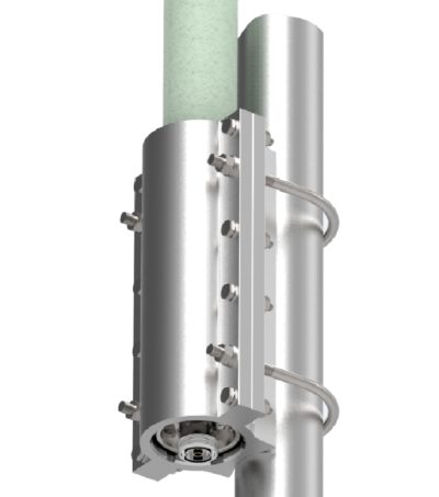
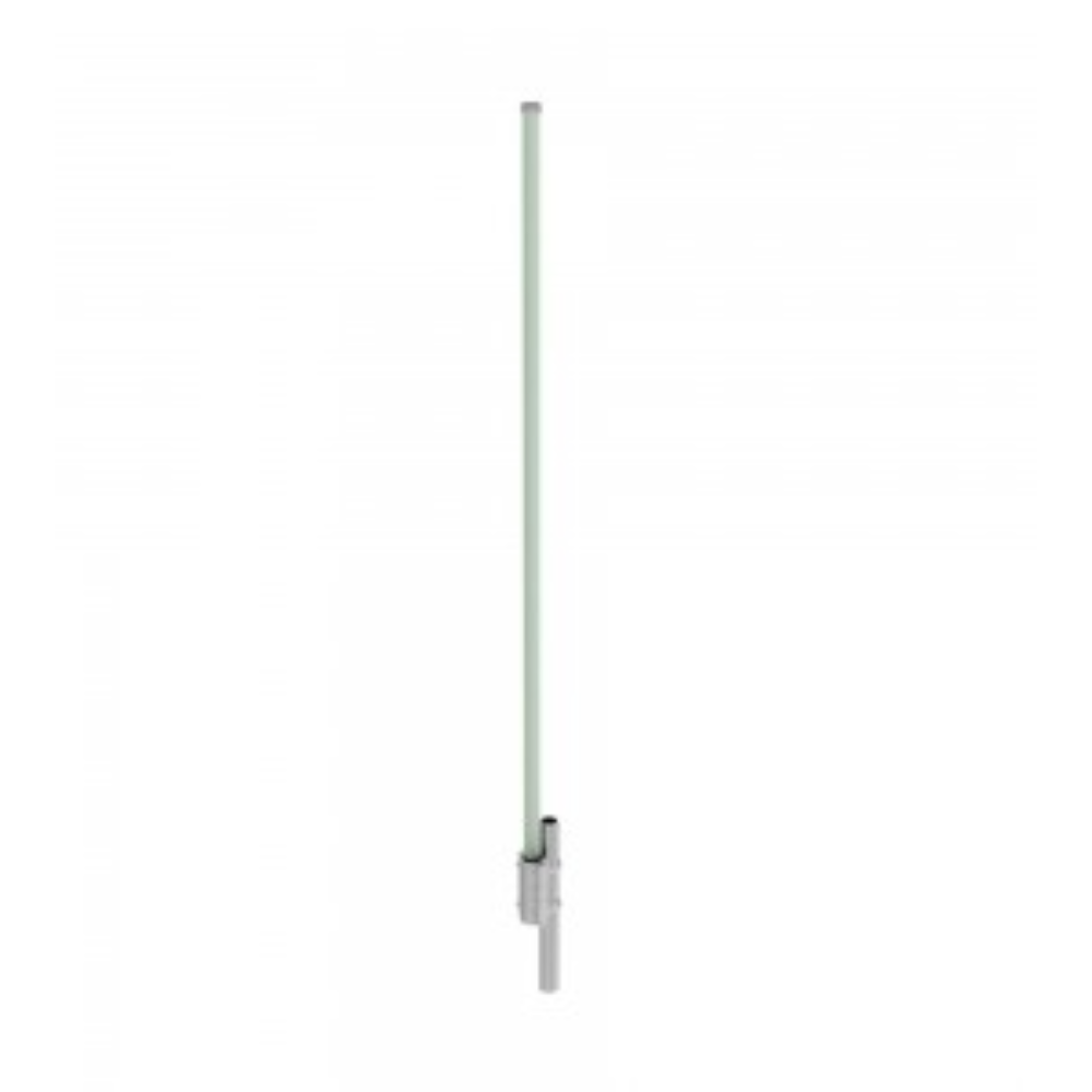
Available in three frequency splits: 746-806; 806-869 or 885-960 within the 746 to 960 MHz range.
- Constructed with a high quality fiberglass light-grey radome
- Aluminum mounting hardware included with the antenna
-
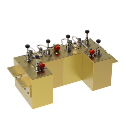
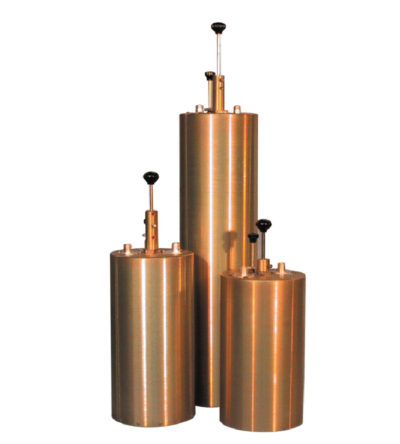
Designed to minimize interference from adjacent channels and outside systems
- Available in single, dual or triple units
- Temperature compensated to ensure frequency stability
- High attenuation
- Adjustable loops: each cavity has a calibration index to reference insertion loss
-
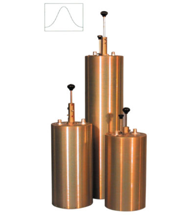
Designed to pass a frequency band and reject a narrow band of frequencies
- Can reject frequencies on either the high or low side of the pass frequency
- Temperature compensated to ensure frequency stability
- High attenuation to minimize desense and interference
-
Ideal for high power, close frequency separation installations
- Designed for combining two frequencies that require extra isolation. Can also be used as efficient pre-selectors
- Temperature compensated to ensure frequency stability
- High attenuation to minimize desense and interference from adjacent systems
- Adjustable loops
-
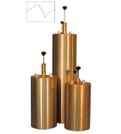
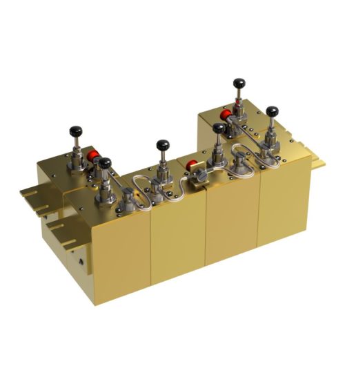
Designed for flexible, close frequency systems
- Each cavity has both a Reject and a Pass band curve
- Available in single units, they can be combined with band pass, notch, and pass reject cavities for added protection and isolation
- Temperature compensated to ensure frequency stability
- High attenuation to minimize desense and interference from adjacent systems
- Adjustable loops: each cavity has a calibration index for easy field tuning
-
Designed for flexible, close frequency systems
- Each cavity has both a Reject and a Pass band curve
- Available in single units, they can be combined with band pass, notch, and pass reject cavities for added protection and isolation
- Temperature compensated to ensure frequency stability
- High attenuation to minimize desense and interference from adjacent systems
- Adjustable loops: each cavity has a calibration index for easy field tuning