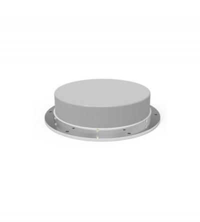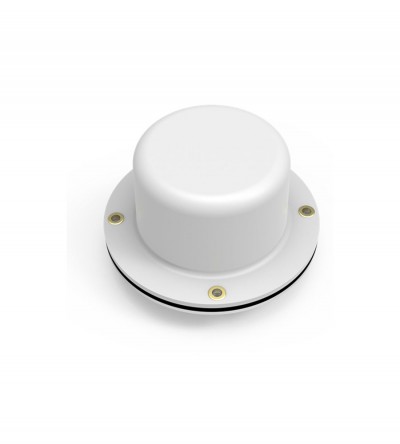
- When mounted on a horizontal surface, maximum radiation is omnidirectional and vertically polarized
- Standard, folded radiator housed in a sturdy high impact ABS radome
- Supplied with a mounting gasket to ensure a moisture-proof installation
-
 Ideal for low clearance applications such as those found on trains, mass transit vehicles, construction equipment and police and emergency vehicles
 -
Ideal for low clearance applications such as those found on trains, mass transit vehicles, construction equipment and police and emergency vehicles
- Compact, low profile antennas in weatherproof ABS radomes
- When mounted on a horizontal surface, maximum radiation is omnidirectional and vertically polarized
- Space diversity design that provides greater communication reliability in a fading environment
- Supplied with an O-ring to ensure a moisture-proof installation
-
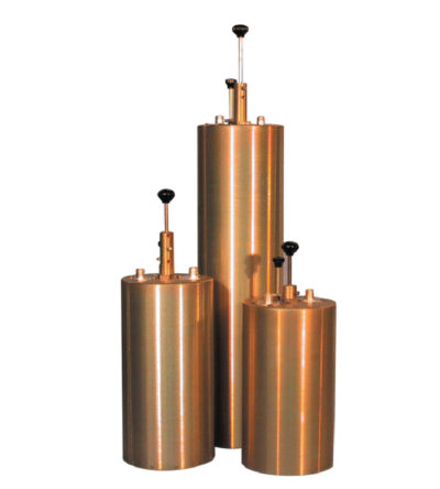
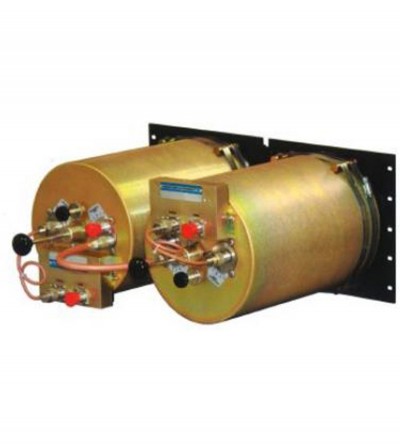
Designed for flexible, close frequency systems
- Each cavity has both a Reject and a Pass band curve
- Available in single units, they can be combined with band pass, notch, and pass reject cavities for added protection and isolation
- Temperature compensated to ensure frequency stability
- High attenuation to minimize desense and interference from adjacent systems
- Adjustable loops: each cavity has a calibration index for easy field tuning
-
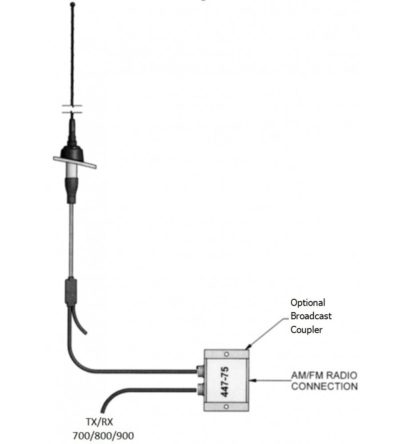
Individually calibrated to ensure the best performance in a disguised appearance
- Two or three separate frequency segments in a given mobile band
- Cross-channel operation in two mobile bands with one antenna
- Alternative antennas to an OEM version will be recommended, where required (e.g. Euro-style, or universal mount traditional whip)
-
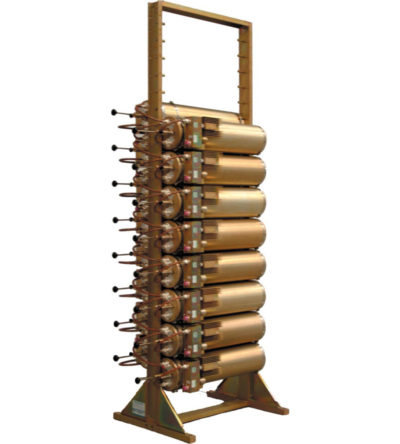
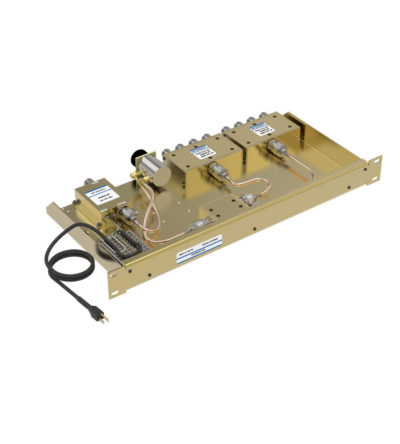
Incorporates expandability, close frequency spacing and some of the lowest insertion losses in the industry
- Can easily support 250 kHz Tx-Tx spacing
- Flexible design: from 1-21 channel capacity
- Expandable: 1 or more additional channels at a time; re-configurable equipment
- 746-1000 MHz, 254 MHz of operating bandwidth
- Temperature compensation to ensure frequency stability
- High attenuation to minimize desense and interference
- Ultra-low insertion losses; low coupling and bridging losses
- Continuous high-power handling capability; 150 watts – 24/7
-
Fully expandable and reconfigurable
- Features X-Pass, plug-and-play technology
- Designed to offer engineers and technicians many options when designing or upgrading a site
-
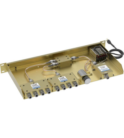
Ideal for combining multiple Rx frequencies onto the same antenna
- Available in 2, 4, 8, 12, 16 and 32
- Simple and cost-effective design
- Standard 19” Rack Mount (RM) or cavity-mounted (CM) versions
- Each unit consists of a power splitter and an RF amplifier.
- Plug-in Power Supply (PS) optional
-
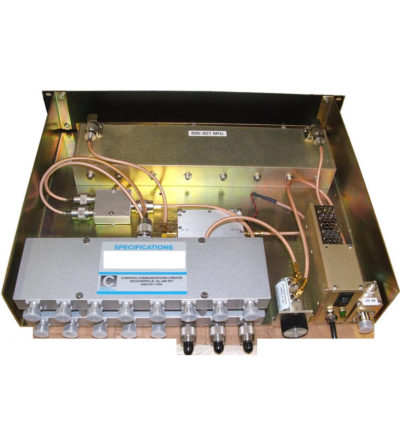
Combines multiple receiver frequencies onto the same antenna
- A low noise amplifier provides gain across the frequency band
- Low noise figure and low intermodulation generation
- Features up to 16 ports (24 and 32 port versions are available)
- -30 dB signal sampler port that can also be used to inject a signal