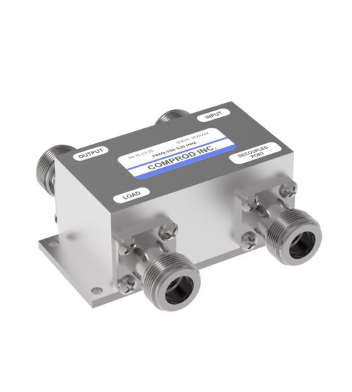
- Low insertion loss
- Excellent return loss
- Compact dimensions saving space
- 3, 4.8, 6, 7, 10, 15, 20 and 30 dB values
- 200 Watts maximum main line power
- Integrated mounting bracket
-
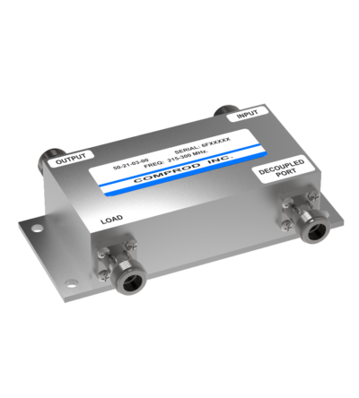
 Multilayer bonded PCB for high performance and compact design
 -
Ideal for combining multiple Rx frequencies onto the same antenna
- Available in 2, 4, 8, 12, 16 and 32 port configurations
- Simple and cost-effective design
- Standard 19” Rack Mount (RM) or cavity-mounted (CM) versions
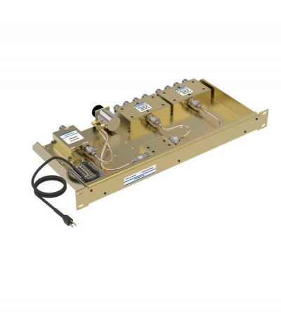
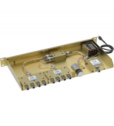
- Each unit consists of a power splitter and an RF amplifier.
- Plug-in Power Supply (PS) optional
-
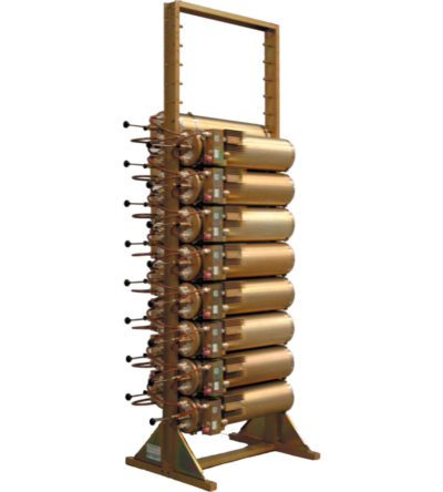
Incorporates expandability, close frequency spacing and some of the lowest insertion losses in the industry
- Can easily support 100 kHz Tx-Tx spacing or 75 kHz spacing while using 10” cavities
- Flexible design: from 1-21 channel capacity
- Expandable: 1 or more additional channels at a time; re-configurable equipment
- 215-300 MHz, 85 MHz of operating bandwidth
- Temperature compensation to ensure frequency stability
- High attenuation to minimize desense and interference
- Ultra-low insertion losses; low coupling and bridging losses
- Continuous high-power handling capability; 150 watts – 24/7
-
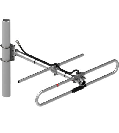
Adjustable, fixed, side or top mount antenna
- Offered in a 1/4, 3/8 or 1/2 wave spacing version
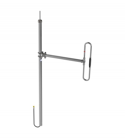
- The 871A-70-2 has external cabling and a field-adjustable pattern.
- The 871F-70-2 has internal cabling and fixed dipole-mast spacing.
- Heavy-duty and black anodized versions available
-
Adjustable, fixed, side or top mount antenna
- Offered in a 1/4, 3/8 or 1/2 wave spacing version
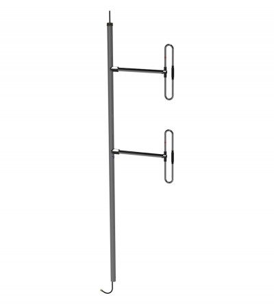
- The 872A-70-2 has external cabling and a field-adjustable pattern.
- The 872F-70-2 has internal cabling and fixed dipole-mast spacing.
- Heavy-duty and black anodized versions available
-
Adjustable, fixed, side or top mount antenna
- Offered in a 1/4, 3/8 or 1/2 wave spacing version
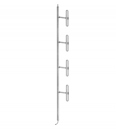
- The 874A-70-2 has external cabling and a field-adjustable pattern.
- The 874F-70-2 has internal cabling and fixed dipole-mast spacing.
- Heavy-duty and black anodized versions available
-
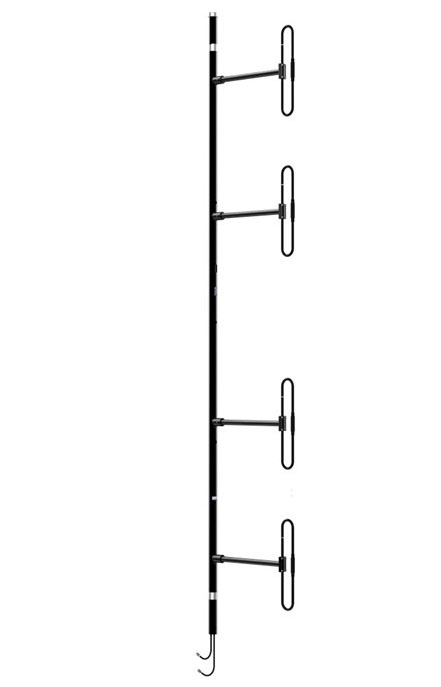
The 876F-70-2HBSP40DF1/2 Black Anodized Heavy Duty Dual Exposed Dipole is well suited for multicoupled RF system. It has an extremely rugged design for use in severe environmental conditions. It has internal cabling and a fix dipole-to-mast spacing. This antenna is a special version of the 876F-70 with increased spacing between the two antennas, giving an isolation of 40 dB. It’s heavy duty and Low PIM design. Our antennas can be configured for side mount or top mount. This antenna is configured for side mount. The 1/2 wave pattern spacing version offer bidirectional pattern with more than 5 dBd Gain at 220 MHz. The 1/4 wave and 3/8 wave versions of the antenna are also available. DOWNLOAD PDF
-
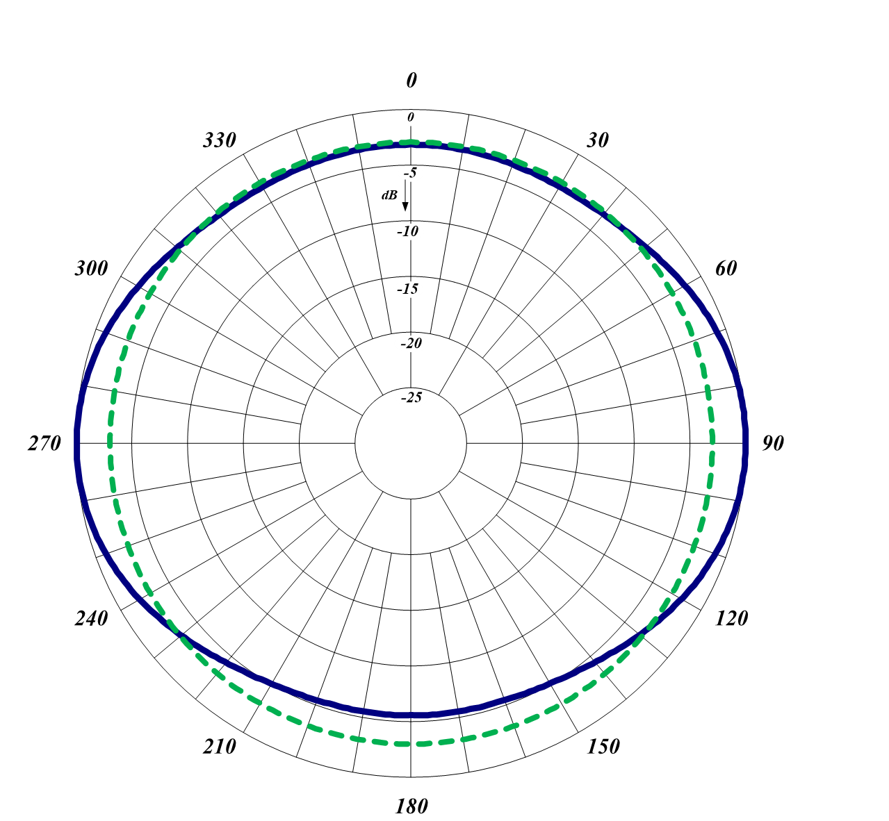
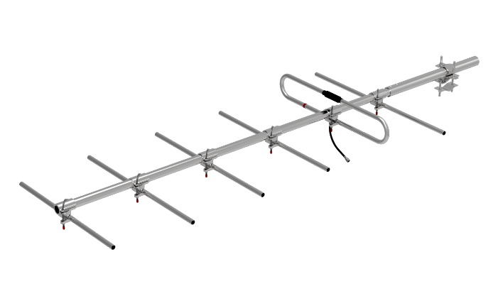
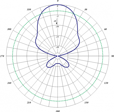
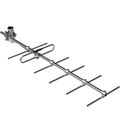
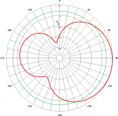
The 290-70-2HDEBNF is Heavy Duty Yagi Antenna with Extended Boom.DOWNLOAD PDF DOWNLOAD DIGITAL PATTERNS
- Each antenna has a rugged design to withstand harsh environmental conditions.
- The mounting hardware supplied will permit either vertical or horizontal polarization.
- The Center Boom (CB) variant is available.
- DC ground for lightning protection.
-
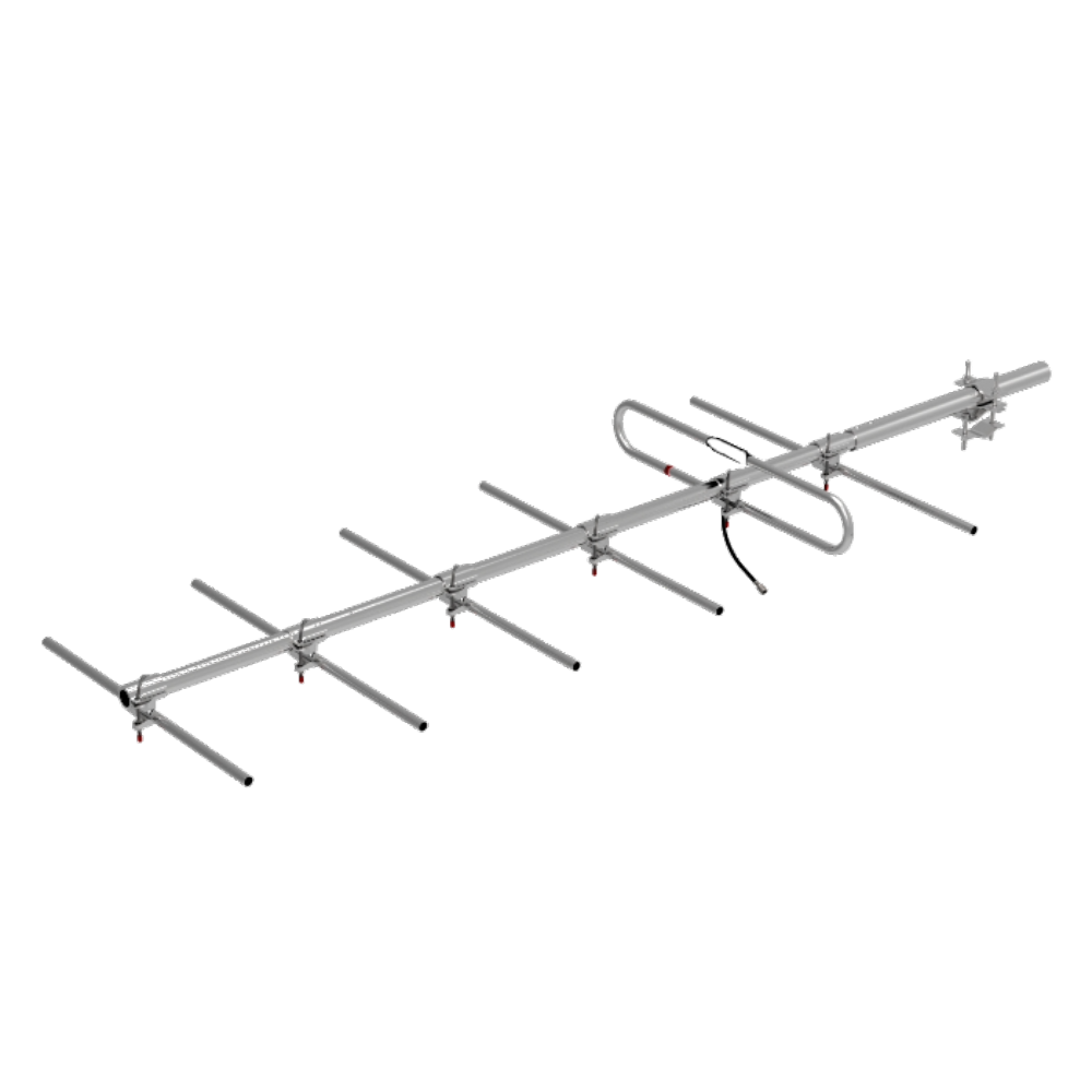
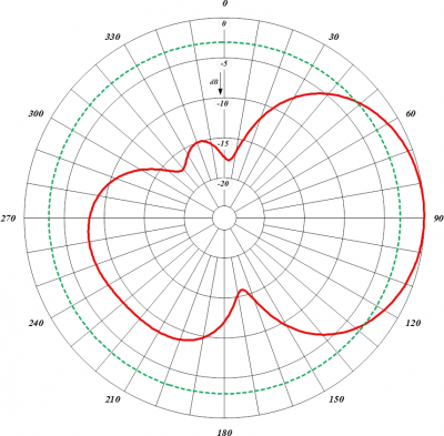
Rugged design to withstand harsh environmental conditionsDOWNLOAD PDF DOWNLOAD DIGITAL PATTERNS
- Vertical or horizontal polarization
- DC ground for lightning protection
- Black anodized and heavy-duty versions available
-
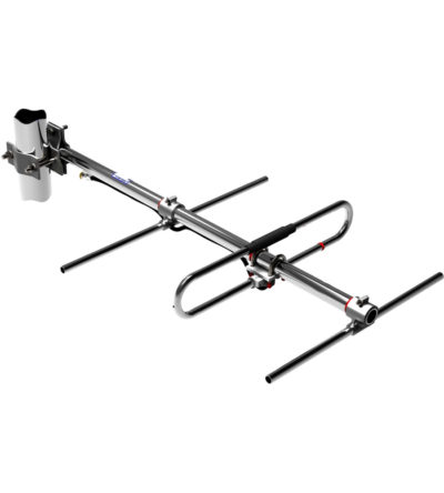
Rugged design to withstand harsh environmental conditions
- Vertical or horizontal polarization
- DC ground for lightning protection
- Black anodized and heavy-duty versions available
-
DOWNLOAD PDF DOWNLOAD DIGITAL PATTERNSRugged design to withstand harsh environmental conditions
- Vertical or horizontal polarization
- DC ground for lightning protection
- Black anodized and heavy-duty versions available