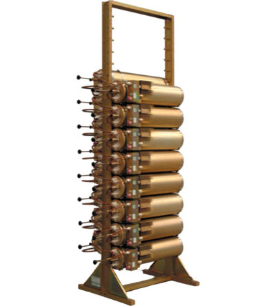
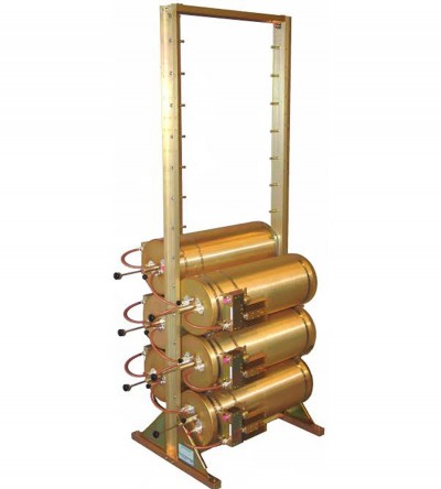
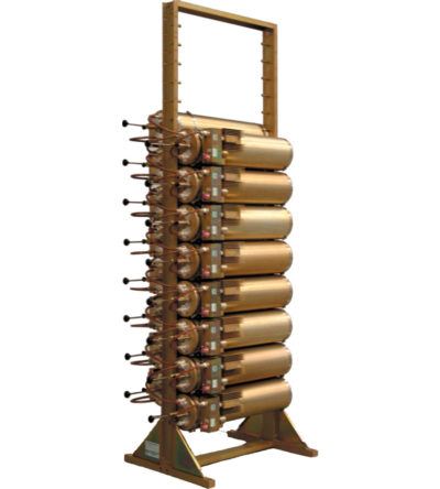
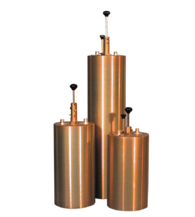
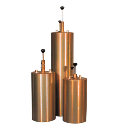
- Can easily support 75 kHz Tx-Tx spacing or 50 kHz spacing while using 10” cavities
- Flexible design: from 1-21 channel capacity
- Expandable: 1 or more additional channels at a time; re-configurable equipment
- 132-174 MHz, 42 MHz of operating bandwidth
- Temperature compensation to ensure frequency stability
- High attenuation to minimize desense and interference
- Ultra-low insertion losses; low coupling and bridging losses
- Continuous high-power handling capability; 150 watts – 24/7
-
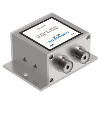
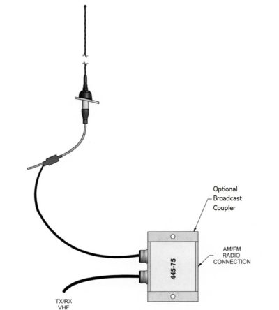
 Comprod is a leader in the design of RF filtering and coupling devices. The following are the specifications for couplers and tuners required as part of a disguised antenna solution.
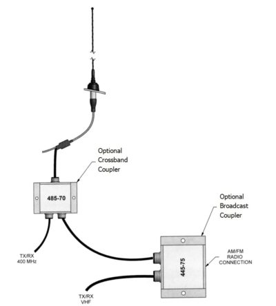
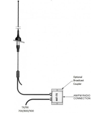
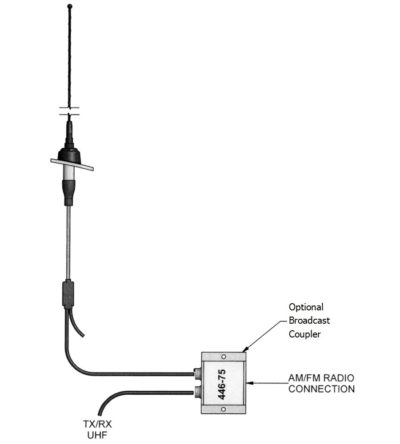
- Broadcast couplers - allow AM-FM broadcast receiver operation along with normal two-way mobile radio operation.
- Crossband couplers - allow mobile radios on two different bands to operate with a single disguised antenna.
- Antenna tuners - provide impedance matching and partly retuning the existing antenna to new frequencies.
-

 Designed to meet customers' special requirements
- Two or three separate frequency segments in a given mobile band
- Cross-channel operation in two mobile bands with one antenna
-
 Individually calibrated to ensure the best performance in a disguised appearance
- Two or three separate frequency segments in a given mobile band
- Cross-channel operation in two mobile bands with one antenna
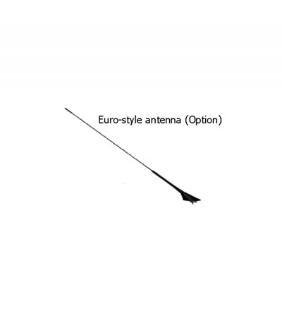
- Alternative antennas to an OEM version will be recommended, where required (e.g. Euro-style, or universal mount traditional whip)
-
 Individually calibrated to ensure the best performance in a disguised appearance
- Two or three separate frequency segments in a given mobile band
- Cross-channel operation in two mobile bands with one antenna
- Alternative antennas to an OEM version will be recommended, where required (e.g. Euro-style, or universal mount traditional whip)
-
 Individually calibrated to ensure the best performance in a disguised appearance
- Two or three separate frequency segments in a given mobile band
- Cross-channel operation in two mobile bands with one antenna
- Alternative antennas to an OEM version will be recommended, where required (e.g. Euro-style, or universal mount traditional whip)
-

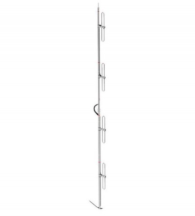
 Light duty VHF exposed dipole
- Available in a VHF configuration (2 frequency splits)
- Low VSWR version with maximum gain over specified frequency
- External cabling and fixed dipole-mast spacing
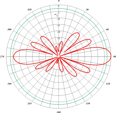
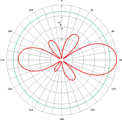
- Adjustable pattern for omnidirectional or offset coverage
- The 834-70 antenna is shipped in two sections to be assembled on site.
-

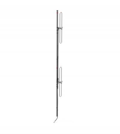
 Light duty VHF exposed dipole
- Available in a VHF configuration (2 frequency splits)
- Low VSWR version with maximum gain over specified frequency
- External cabling and fixed dipole-mast spacing
- Adjustable pattern for omnidirectional or offset coverage

