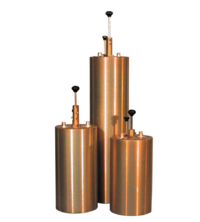
- Extruded aluminum cavities and solid- shield copper-jacketed inter-cabling that ensures excellent mechanical and electrical stability
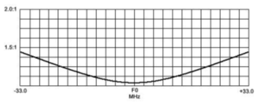
- All units are adjustable in the field and rated at 50 watts continuous duty with a maximum VSWR of 1.5: 1 over the entire tuning range.
- BNC connectors are standard.
-
 Features compact size, low loss and temperature compensation over the range of -40ºC to +60ºC
 -
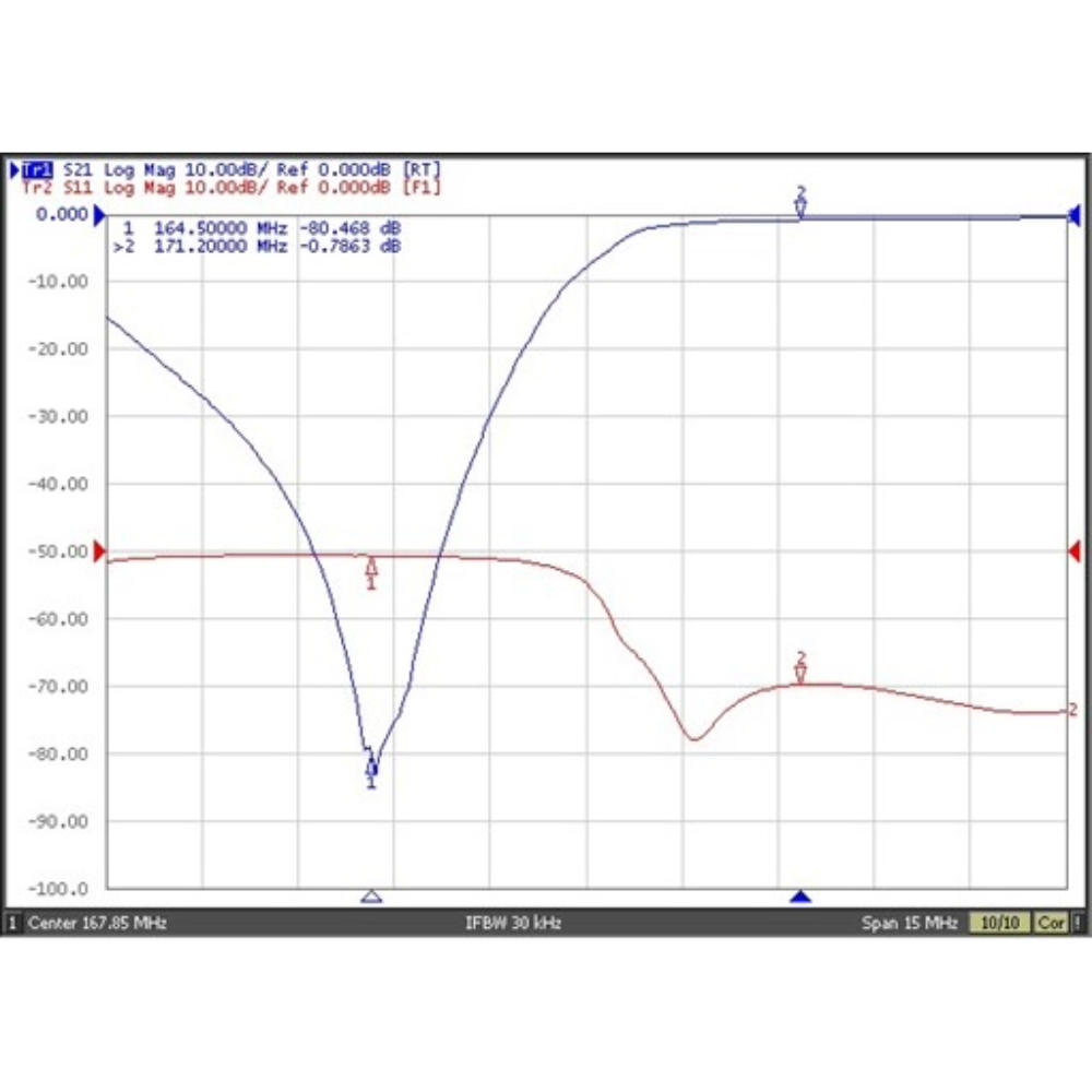
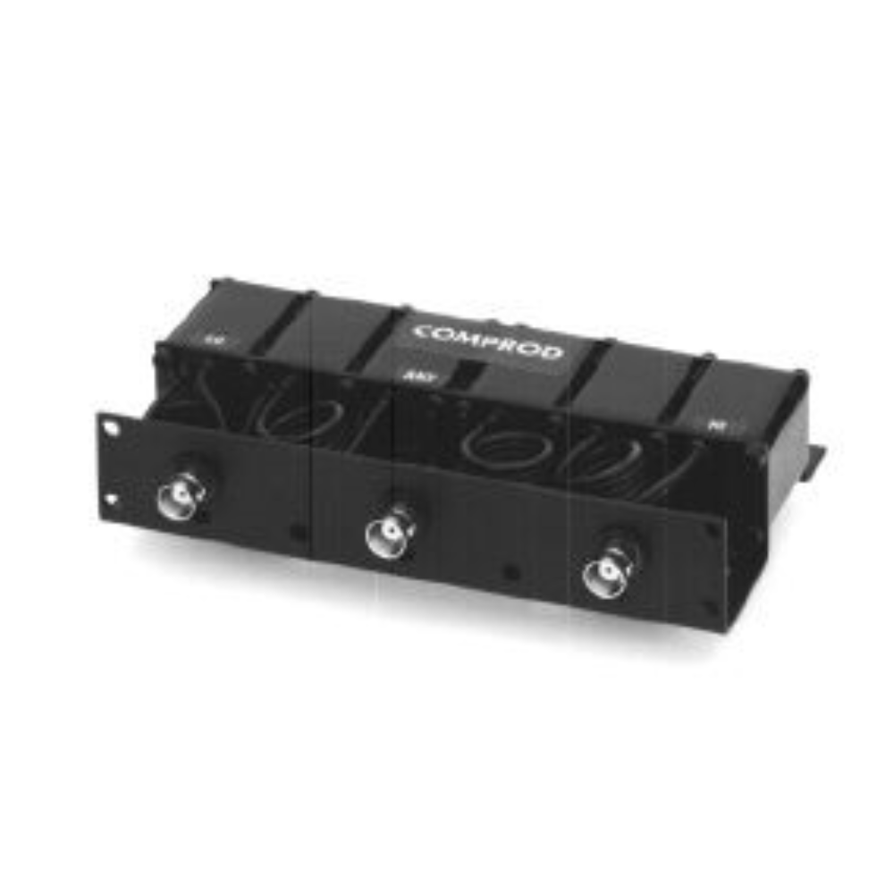
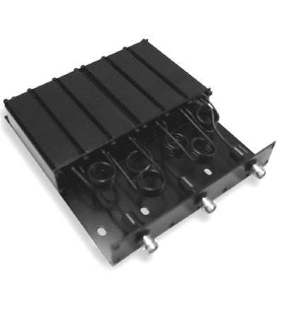
The Comprod 526-90 is a 1 inch 6 cavity VHF compact size mobile duplexer. Featuring low loss and temperature compensation over the range of -22 F to +140 F. The use of extruded aluminum cavities and solid shield copper jacketed inter-cabling assure excellent mechanical and electrical stability.
- All units are field tunable and rated at 50 watts continuous duty
- BNC connectors are standard.
-
The Comprod 544-90*1 is a 1 inch 4 cavity UHF compact size mobile duplexer. Featuring low loss and temperature compensation over the range of -22 F to +140 F. The use of extruded aluminum cavities and solid shield copper jacketed inter-cabling assure excellent mechanical and electrical stability.
- All units are field tunable and rated at 50 watts continuous duty
- BNC connectors are standard.
- Variations on connectors and mountings are available on special order.
-
The Comprod 544-90*2 is a 1 inch 4 cavity UHF compact size mobile duplexer. Featuring low loss and temperature compensation over the range of -22 F to +140 F. The use of extruded aluminum cavities and solid shield copper jacketed inter-cabling assure excellent mechanical and electrical stability.
- All units are field tunable and rated at 50 watts continuous duty
- BNC connectors are standard.
- Variations on connectors and mountings are available on special order.
-
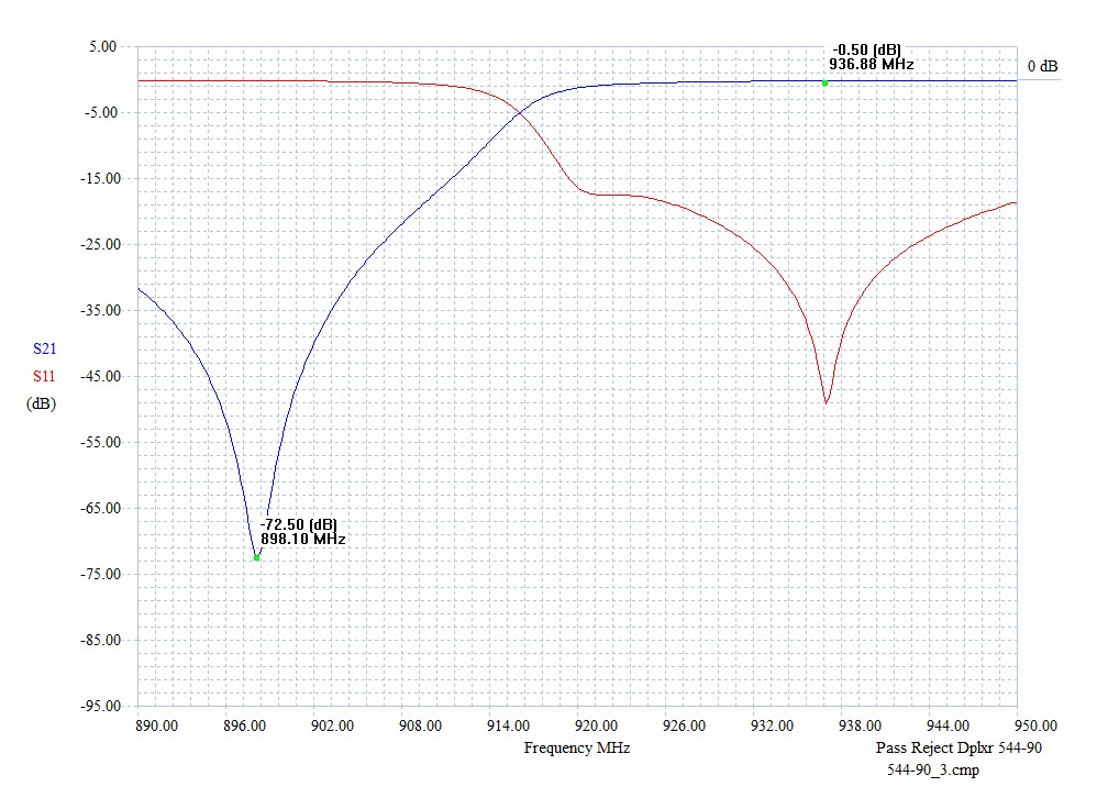
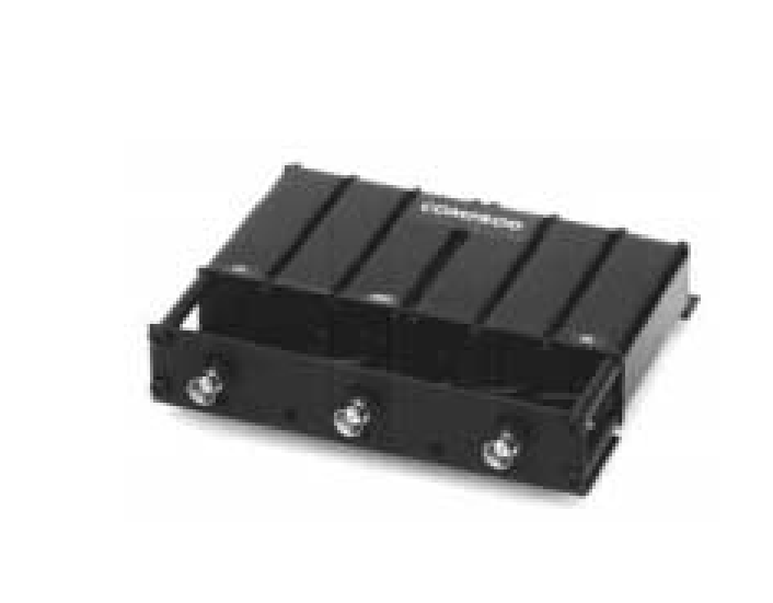
The Comprod 544-90*3 is a 1 inch 4 cavity UHF compact size mobile duplexer. Featuring low loss and temperature compensation over the range of -22 F to +140 F. The use of extruded aluminum cavities and solid shield copper jacketed inter-cabling assure excellent mechanical and electrical stability.
- All units are field tunable and rated at 50 watts continuous duty
- BNC connectors are standard.
- Variations on connectors and mountings are available on special order.
-
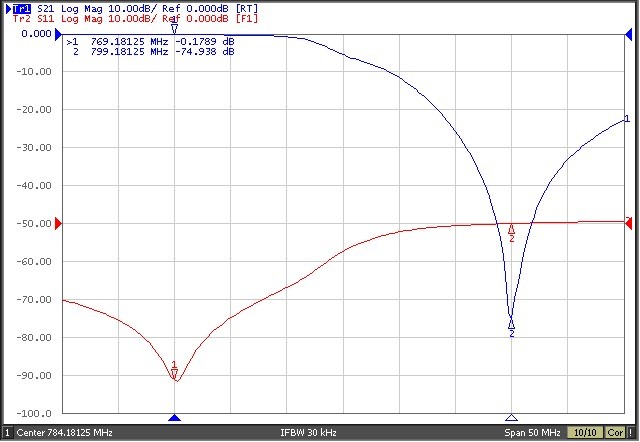
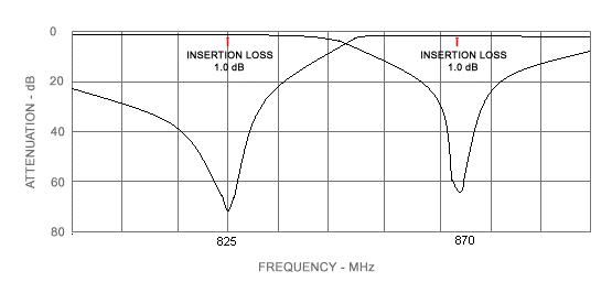
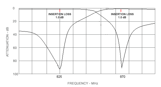
Our line of 800 MHz mobile duplexers feature compact size, low loss and temperature compensation over the range of -22 oF to +140 oF. The use of extruded aluminum cavities and solid shield copper jacketed inter-cabling assure excellent mechanical and electrical stability.
- All units are field tunable and rated at 50 watts continuous duty
- BNC connectors are standard.
- Variations on connectors and mountings are available on special order.
-
Ideal for low clearance applications such as those found on trains, mass transit vehicles, construction equipment and police and emergency vehicles
- When mounted on a horizontal surface, maximum radiation is omnidirectional and vertically polarized
- Standard, folded radiator housed in a sturdy high impact ABS radome
- Supplied with a mounting gasket to ensure a moisture-proof installation
-
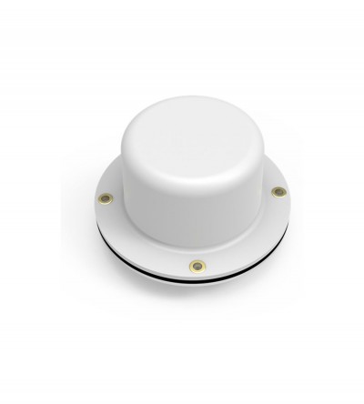
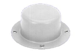
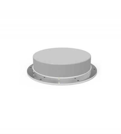
Our line of radome transit antennas for operation in the 806-960 MHz band consists of compact, low profile antennas in weatherproof ABS radomes. When mounted on a horizontal surface, maximum radiation is omnidirectional and vertically polarized. These antennas are an excellent choice for low clearance applications such as those found on trains, mass transit vehicles, construction equipment and police and emergency vehicles. The F-3758 model is a standard, folded radiator housed in a sturdy high-impact ABS radome. To ensure a moisture proof installation, the F-3758 model is supplied with a mounting gasket. DOWNLOAD PDF
-
Ideal for low clearance applications such as those found on trains, mass transit vehicles, construction equipment and police and emergency vehicles
- Compact, low profile antennas in weatherproof ABS radomes
- When mounted on a horizontal surface, maximum radiation is omnidirectional and vertically polarized
- Space diversity design that provides greater communication reliability in a fading environment
- Supplied with an O-ring to ensure a moisture-proof installation
-
Designed for flexible, close frequency systems
- Each cavity has both a Reject and a Pass band curve
- Available in single units, they can be combined with band pass, notch, and pass reject cavities for added protection and isolation
- Temperature compensated to ensure frequency stability
- High attenuation to minimize desense and interference from adjacent systems
- Adjustable loops: each cavity has a calibration index for easy field tuning
-
Individually calibrated to ensure the best performance in a disguised appearance
- Two or three separate frequency segments in a given mobile band
- Cross-channel operation in two mobile bands with one antenna
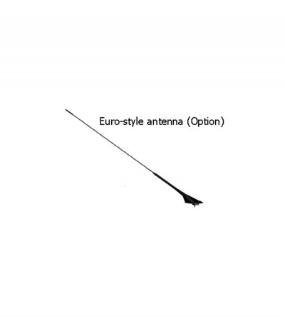
- Alternative antennas to an OEM version will be recommended, where required (e.g. Euro-style, or universal mount traditional whip)
-
Designed for flexible, close frequency systems
- Each cavity has both a Reject and a Pass band curve
- Available in single units, they can be combined with band pass, notch, and pass reject cavities for added protection and isolation
- Temperature compensated to ensure frequency stability
- High attenuation to minimize desense and interference from adjacent systems
- Adjustable loops: each cavity has a calibration index for easy field tuning
-
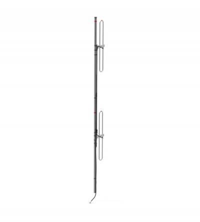
Light duty VHF exposed dipole
- Available in a VHF configuration (2 frequency splits)
- Low VSWR version with maximum gain over specified frequency
- External cabling and fixed dipole-mast spacing
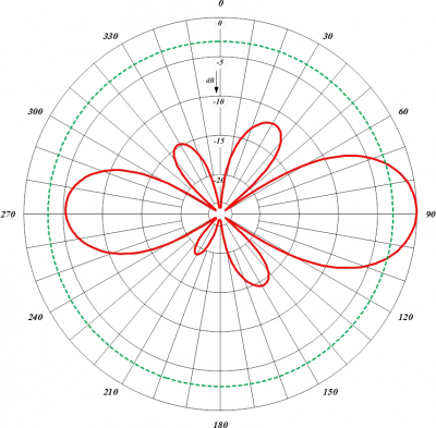
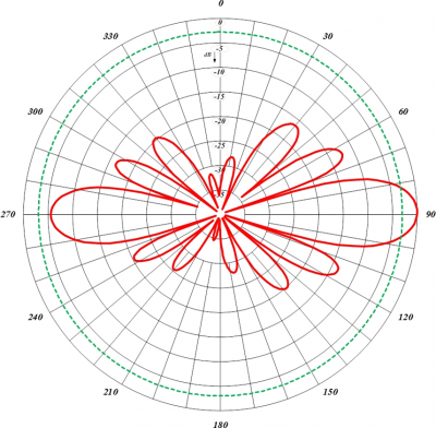
- Adjustable pattern for omnidirectional or offset coverage
-
Light duty VHF exposed dipole
- Available in a VHF configuration (2 frequency splits)
- Low VSWR version with maximum gain over specified frequency
- External cabling and fixed dipole-mast spacing
- Adjustable pattern for omnidirectional or offset coverage
- The 834-70 antenna is shipped in two sections to be assembled on site.
-
Designed for flexible, close frequency systems
- Each cavity has both a Reject and a Pass band curve
- Available in single units, they can be combined with band pass, notch, and pass reject cavities for added protection and isolation
- Temperature compensated to ensure frequency stability
- High attenuation to minimize desense and interference from adjacent systems
- Adjustable loops: each cavity has a calibration index for easy field tuning
-
Individually calibrated to ensure the best performance in a disguised appearance
- Two or three separate frequency segments in a given mobile band
- Cross-channel operation in two mobile bands with one antenna
- Alternative antennas to an OEM version will be recommended, where required (e.g. Euro-style, or universal mount traditional whip)
-
Designed for flexible, close frequency systems
- Each cavity has both a Reject and a Pass band curve
- Available in single units, they can be combined with band pass, notch, and pass reject cavities for added protection and isolation
- Temperature compensated to ensure frequency stability
- High attenuation to minimize desense and interference from adjacent systems
- Adjustable loops: each cavity has a calibration index for easy field tuning
-
Individually calibrated to ensure the best performance in a disguised appearance
- Two or three separate frequency segments in a given mobile band
- Cross-channel operation in two mobile bands with one antenna
- Alternative antennas to an OEM version will be recommended, where required (e.g. Euro-style, or universal mount traditional whip)
-
Designed to meet customers' special requirements
- Two or three separate frequency segments in a given mobile band
- Cross-channel operation in two mobile bands with one antenna
-
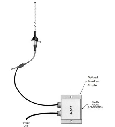
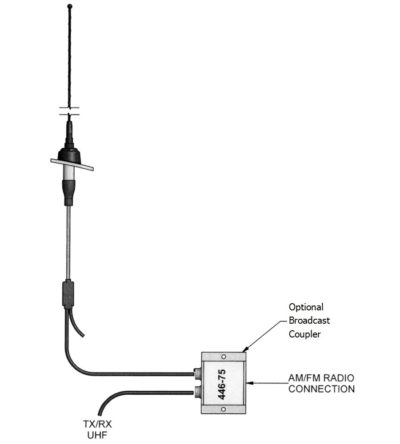
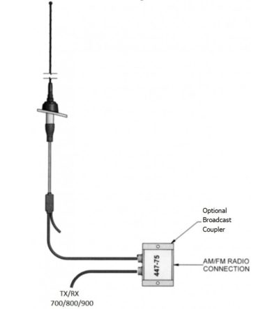
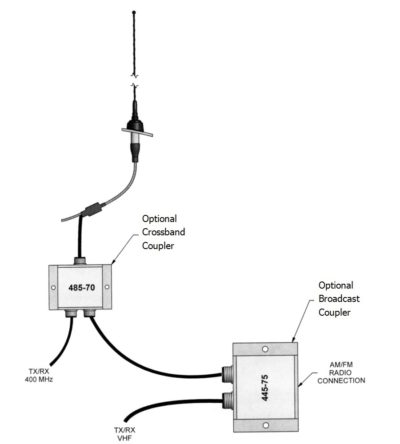
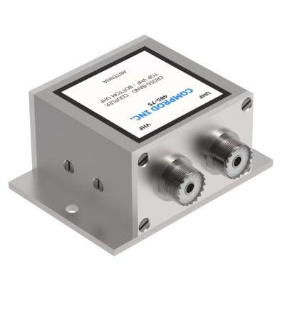
Comprod is a leader in the design of RF filtering and coupling devices. The following are the specifications for couplers and tuners required as part of a disguised antenna solution.
- Broadcast couplers - allow AM-FM broadcast receiver operation along with normal two-way mobile radio operation.
- Crossband couplers - allow mobile radios on two different bands to operate with a single disguised antenna.
- Antenna tuners - provide impedance matching and partly retuning the existing antenna to new frequencies.
-
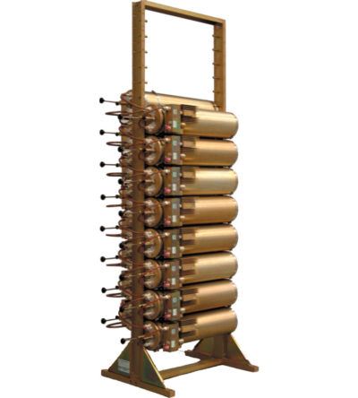
Incorporates expandability, close frequency spacing and some of the lowest insertion losses in the industry
- Can easily support 75 kHz Tx-Tx spacing or 50 kHz spacing while using 10” cavities
- Flexible design: from 1-21 channel capacity
- Expandable: 1 or more additional channels at a time; re-configurable equipment
- 108-136 MHz, 28 MHz of operating bandwidth
- Temperature compensation to ensure frequency stability
- High attenuation to minimize desense and interference
- Ultra-low insertion losses; low coupling and bridging losses
- Continuous high-power handling capability; 150 watts – 24/7
-
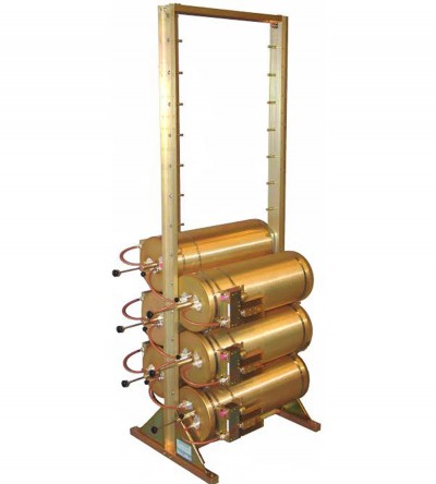
Incorporates expandability, close frequency spacing and some of the lowest insertion losses in the industry
- Can easily support 75 kHz Tx-Tx spacing or 50 kHz spacing while using 10” cavities
- Flexible design: from 1-21 channel capacity
- Expandable: 1 or more additional channels at a time; re-configurable equipment
- 132-174 MHz, 42 MHz of operating bandwidth
- Temperature compensation to ensure frequency stability
- High attenuation to minimize desense and interference
- Ultra-low insertion losses; low coupling and bridging losses
- Continuous high-power handling capability; 150 watts – 24/7