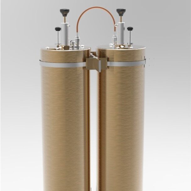
- Available in single, dual, triple or additional units
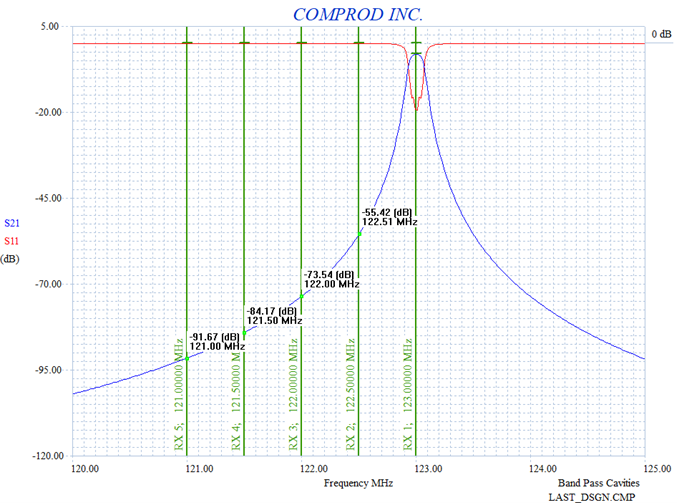
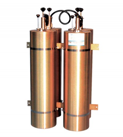
- Temperature compensated to ensure frequency stability
- High attenuation to minimize desense and interference from adjacent systems
- Adjustable loops: each cavity has a calibration index for easy field tuning
-

 Designed for minimizing interference from adjacent channels and outside systems
 -

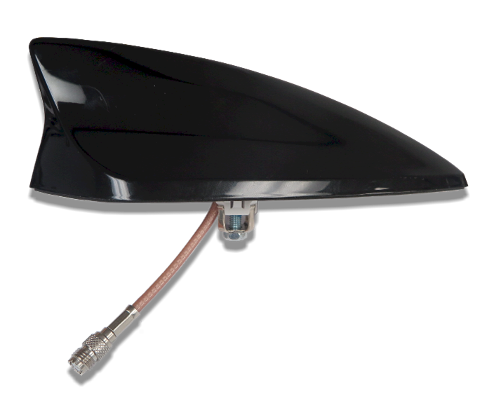
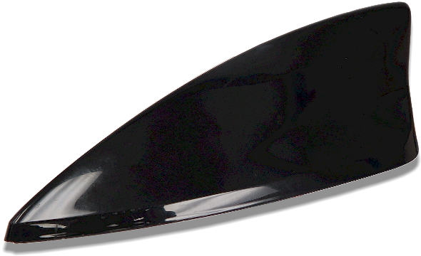
 The F-33499 is a Covert Vehicle Antenna disguised in Shark Fin housing. This antenna provides 0 dBd of gain and less than 1.7:1 VSWR over 10 MHz bandwidth in the range of frequency of 406 to 470MHz. It has a radiation pattern nearly omnidirectional in azimuth. The shark fin style disguised antennas allow a public security organization to use a vehicle’s existing AM/FM antennas for both conventional radio receiver functions as well as allowing a two-way radio to communicate over the same antenna. This allows a covert vehicle to avoid the need for a long mobile antenna.
- 0 dBd of gain
- Less than 1.7:1 VSWR over its operating bandwidth
- A radiation pattern nearly omnidirectional in azimuth
- A broadcast coupler is optionally available
- Cross-band couplers when multi-band operation required on a single antenna
-

 The F-33496 is a Covert Vehicle Antenna disguised in Shark Fin housing. The shark fin style disguised antennas allow a public security organization to use a vehicle’s existing AM/FM antennas for both conventional radio receiver functions as well as allowing a two-way radio to communicate over the same antenna. This allows a covert vehicle to avoid the need for a long mobile antenna. A broadcast coupler is optionally available, to allow the two- way radio transmit and receive frequencies to be shared with the vehicle’s AM/FM radio. The coupler prevents the transmit radio from damaging the AM/FM radio.
- 0 dBd of gain
- Less than 1.7:1 VSWR over its operating bandwidth
- A radiation pattern nearly omnidirectional in azimuth
- A broadcast coupler is optionally available
- Cross-band couplers when multi-band operation required on a single antenna
-


- Provides a dual band frequency range of 700/800 MHz or 800/900 MHz Public Safety bands.
- 2.0 dBd gain achieved over its operating bandwidth
- Manufactured using the best corrosion-resistant materials and finishes available
- Ultrasonically-welded brass insert and leaf spring-loaded contact for long-term reliability
- Standard NMO type mount providing an excellent moisture seal even when the antenna is removed
-


- Frequency range of 138-174 MHz
- Unity gain achieved over its operating bandwidth
- Used for vehicles, such as ambulances, where vertical clearance is critical
- This antenna is ideal for a vehicle that enters areas with reduced headroom
- Combined with a matching circuit that is mounted inside the vehicle
- Each antenna assembly is individually calibrated on the roof of a vehicle
-

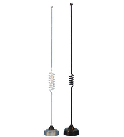
- 3.0 dBd gain achieved by featuring a 5/8-wave above a ¼ wave design
- Manufactured using the best corrosion-resistant materials and finishes available
- Ultrasonically-welded brass insert and leaf spring-loaded contact for long-term reliability
- Standard NMO type mount providing an excellent moisture seal even when the antenna is removed
-
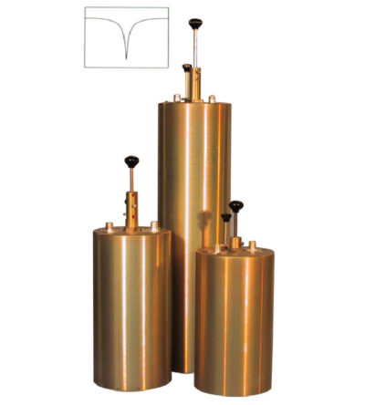
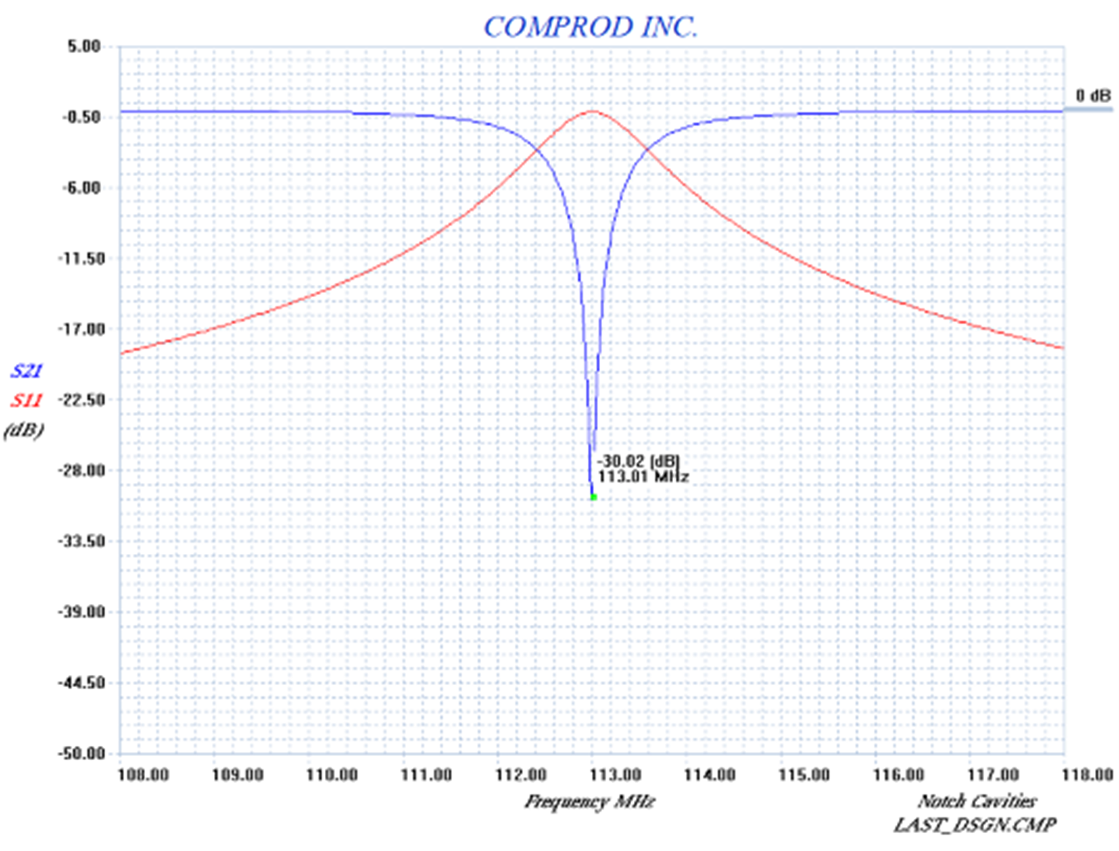
 Designed to reject one narrow band of frequencies, while letting all others pass in the operating band
- Can be cascaded or added to one another in order to sharpen the attenuation of the rejection curve
- Temperature compensated to ensure frequency stability
- High attenuation to minimize desense and interference from adjacent systems
- Adjustable loops: each cavity has a calibration index
-

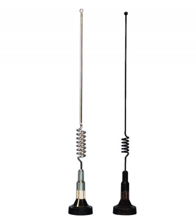
- 3.0 dBd gain achieved by featuring a 5/8-wave above a ¼ wave open coil design
- Manufactured using the best corrosion-resistant materials and finishes available
- Ultrasonically-welded brass insert and leaf spring-loaded contact for long-term reliability
- Standard NMO type mount providing an excellent moisture seal even when the antenna is removed
-
 Designed to reject one narrow band of frequencies, while letting all others pass in the operating band
- Can be cascaded or added to one another in order to sharpen the attenuation of the rejection curve
- Temperature compensated to ensure frequency stability
- High attenuation to minimize desense and interference from adjacent systems
- Adjustable loops: each cavity has a calibration index
-
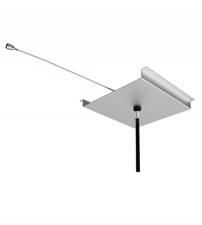
 Designed for external Public Safety Radio Frequencies to propagate within buildings, tunnels or public use environments
- Designed for mounting on a concrete surface to meet full bandwidth specifications
- Meet the recommended fire safety practices of both the Federal Transit Administration (FTA) and the Federal Rail Administration (FRA) for smoke emission and flammability as tested under ASTM E-662 and ASTM E-162
- Flame resistant and self-extinguishing polycarbonate tubing is used for the radome
-

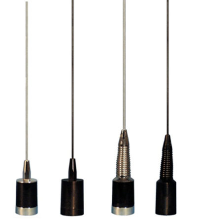
- 3.0 dBd gain achieved by featuring a 5/8-wave whip with a base loaded matching coil
- Manufactured using the best corrosion-resistant materials and finishes available
- Triple-plated chrome brass with a large insert molded low-loss coil form and spring-loaded, gold-plated contact
- Large diameter coil form which allows for a wider operational bandwidth and better matching characteristics
- Rubber boot and overlap construction to ensure a moisture-proof installation
- Standard Motorola NMO type mount
-

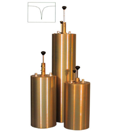
 Designed to reject one narrow band of frequencies, while letting all others pass in the operating band
- Can be cascaded or added to one another in order to sharpen the attenuation of the rejection curve
- Temperature compensated to ensure frequency stability
- High attenuation to minimize desense and interference from adjacent systems
- Adjustable loops: each cavity has a calibration index

