- Can be cascaded or added to one another in order to sharpen the attenuation of the rejection curve
- Temperature compensated to ensure frequency stability
- High attenuation to minimize desense and interference from adjacent systems
- Adjustable loops: each cavity has a calibration index
-
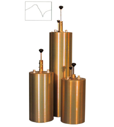
 Designed to reject one narrow band of frequencies, while letting all others pass in the operating band
 -
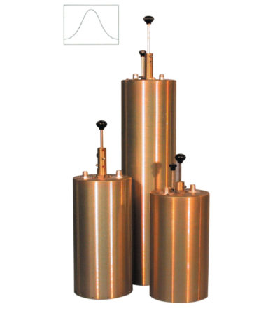
Designed to pass a frequency band and reject a narrow band of frequencies
- Can reject frequencies on either the high or low side of the pass frequency
- Temperature compensated to ensure frequency stability
- High attenuation to minimize desense and interference
-
Designed to pass a frequency band and reject a narrow band of frequencies
- Can reject frequencies on either the high or low side of the pass frequency
- Temperature compensated to ensure frequency stability
- High attenuation to minimize desense and interference
-
Designed to pass a frequency band and reject a narrow band of frequencies
- Can reject frequencies on either the high or low side of the pass frequency
- Temperature compensated to ensure frequency stability
- High attenuation to minimize desense and interference
-
Designed to pass a frequency band and reject a narrow band of frequencies
- Can reject frequencies on either the high or low side of the pass frequency
- Temperature compensated to ensure frequency stability
- High attenuation to minimize desense and interference
-
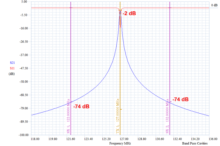
Designed to minimize interference from adjacent channels and outside systems
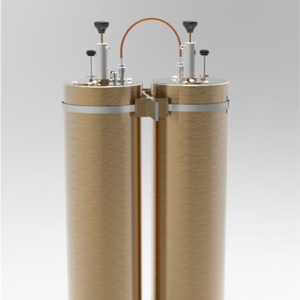
- Available in single, dual or triple units
- Temperature compensated to ensure frequency stability
- High attenuation
- Adjustable loops: each cavity has a calibration index to reference insertion loss
-
Designed to minimize interference from adjacent channels and outside systems
- Available in single, dual or triple units
- Temperature compensated to ensure frequency stability
- High attenuation
- Adjustable loops: each cavity has a calibration index to reference insertion loss
-
Designed to minimize interference from adjacent channels and outside systems
- Available in single, dual or triple units
- Temperature compensated to ensure frequency stability
- High attenuation
- Adjustable loops: each cavity has a calibration index to reference insertion loss
-
Designed to minimize interference from adjacent channels and outside systems
- Available in single, dual or triple units
- Temperature compensated to ensure frequency stability
- High attenuation
- Adjustable loops: each cavity has a calibration index to reference insertion loss
-
Designed to minimize interference from adjacent channels and outside systems
- Available in single, dual or triple units
- Temperature compensated to ensure frequency stability
- High attenuation
- Adjustable loops: each cavity has a calibration index to reference insertion loss
-
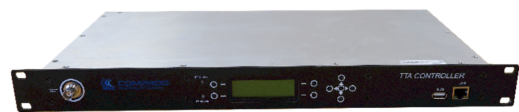
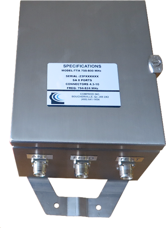
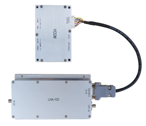
Top-Tower Amplifier Our modular Tower-Top Amplifier (TTA) systems provide superior receiver system performance and excellent electrical reliability by improving base station Up Link (UL) sensitivity. TTA systems overcome link budget imbalance between the Up Link and Down Link (DL) by boosting received signal to overcome received path loss (feeder losses).
- Improved base station UL sensitivity
- Redundant LNA with automatic change over
- LNA bypass modes
- Monitoring & Control via GUI
- SNMP Alarms
- Remote Access
-
Model: 58-70-32-ATT-DC (700-1000 MHz) In case of failure (DC off or out of range), the RF signal is bypassed, dry contact and red LED alarm are activated.
- Designed for unconditionally stable performance in professional communications systems
- Featuring rugged construction