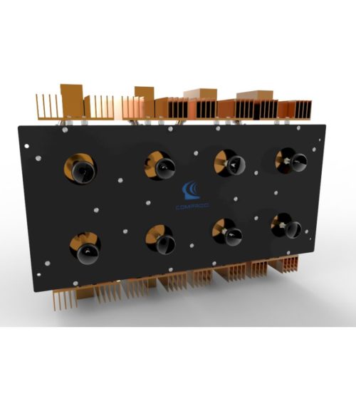
- Available in 2, 4, 8, 12, 16 and 32 port configurations
- Simple and cost-effective design
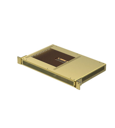
- Standard 19” Rack Mount (RM) or cavity-mounted (CM) versions
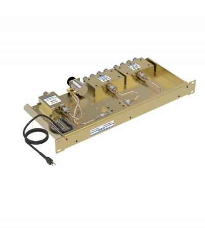
- Each unit consists of a power splitter and an RF amplifier.
- Plug-in Power Supply (PS) optional
-
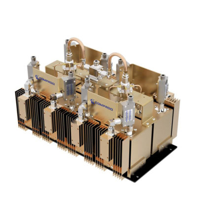
 Ideal for combining multiple Rx frequencies onto the same antenna
 -
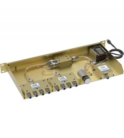
Combines multiple receiver frequencies onto the same antenna
- A low noise amplifier provides gain across the frequency band
- Low noise figure and low intermodulation generation
- Features up to 16 ports (24 and 32 port versions are available)
- -30 dB signal sampler port that can also be used to inject a signal
-
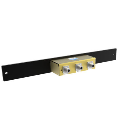
Designed for easy installation, reducing coaxial runs, and in-building applications with multi-band antennas
- Allows multiple bands to share the same transmission lines
- Available in VHF, UHF and 800/900 MHz bands
- Can be Tower-Mounted (TM), Rack-Mounted (RM) or stand alone
-
Designed for easy installation, reducing coaxial runs, and in-building applications with multi-band antennas
- Allows multiple bands to share the same transmission lines
- Available in VHF, UHF and 800/900 MHz bands
- Can be Tower-Mounted (TM), Rack-Mounted (RM) or stand alone
-
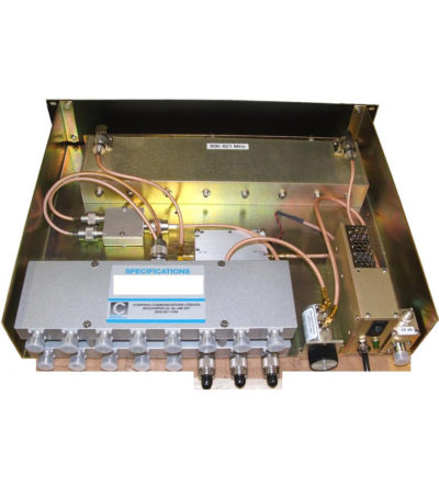
Fully expandable and reconfigurable
- Features X-Pass, plug-and-play technology
- Designed to offer engineers and technicians many options when designing or upgrading a site
-
Dielectric resonator technology resulting in higher performance than standard RF cavities in a much smaller package
- Available for the 764-776, 851-869 and 935-941 MHz bands
- Designed for tight channel spacing
- Lowest insertion loss, high isolation for maximum coverage and reduced interference
- Easy field expandability with X-Pass technology - one channel at a time
- Compact, robust design for rapid installations, increased mobility and ease of maintenance
-
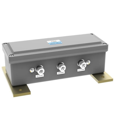
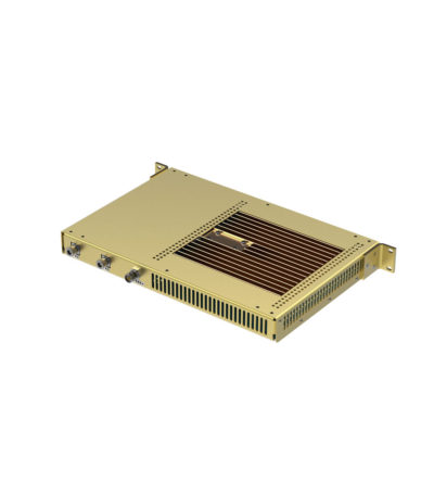
Our Control Station Combiners (CSC) is an ideal solution to reduce the number of antennas required on a communications site by maintaining a high radio-to-radio isolation at all times. It can significantly reduce tower clutter and loading, and simplify cabling installation at control center facilities. This product provides frequency-agile operation across a frequency range from 136 up to 174 MHz. This combiner has the possibilities to be connected to two antennas TX and RX. In case of only one antenna is used for TX and RX, an external duplexer is required. DOWNLOAD PDF
-
Our Control Station Combiners (CSC) is an ideal solution to reduce the number of antennas required on a communications site by maintaining a high radio-to-radio isolation at all times. It can significantly reduce tower clutter and loading, and simplify cabling installation at control center facilities. This product provides frequency-agile operation across a frequency range from 380 up to 512 MHz. This combiner has the possibilities to be connected to two antennas TX and RX. In case of only one antenna is used for TX and RX, an external duplexer is required. DOWNLOAD PDF
-
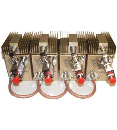
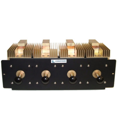
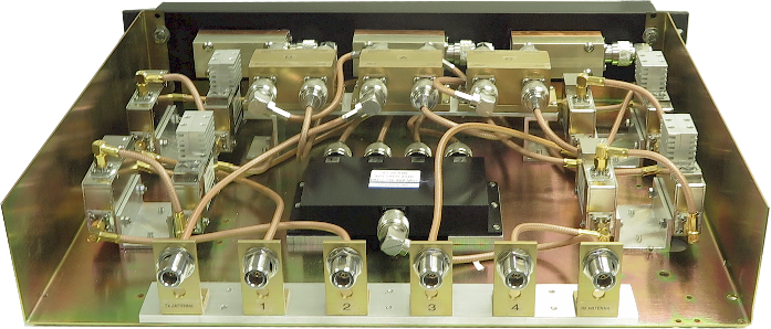
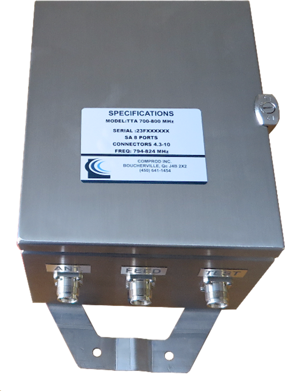
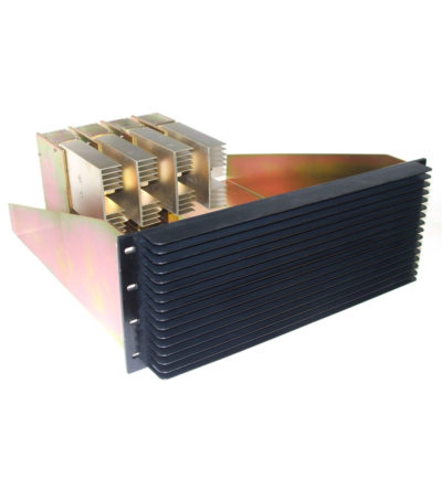
Top-Tower Amplifier Our modular Tower-Top Amplifier (TTA) systems provide superior receiver system performance and excellent electrical reliability by improving base station Up Link (UL) sensitivity. TTA systems overcome link budget imbalance between the Up Link and Down Link (DL) by boosting received signal to overcome received path loss (feeder losses).
- Improved base station UL sensitivity
- Redundant LNA with automatic change over
- LNA bypass modes
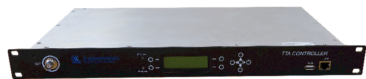
- Monitoring & Control via GUI
- SNMP Alarms
- Remote Access
-
Dielectric resonator technology resulting in higher performance than standard RF cavities in a much smaller package
- Available for the 764-776, 851-869 and 935-941 MHz bands
- Designed for tight channel spacing
- Lowest insertion loss, high isolation for maximum coverage and reduced interference
- Star configuration
- Compact, robust design for rapid installations, increased mobility and ease of maintenance
-
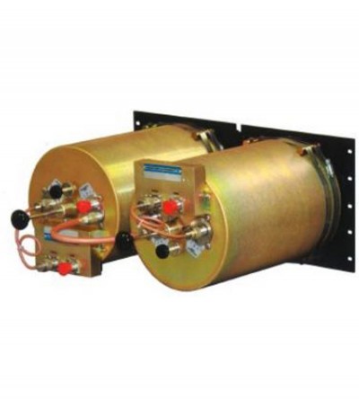
Designed for compact, close frequency installations. Ideal for very closely spaced frequency transmitters
- High isolation: minimizes intermodulation products
- Low loss: maximizes system performance
- Continuous power:
- Physical size and materials used maximizes the performance across the operating band
-
Designed for compact, close frequency installations. Ideal for very closely spaced frequency transmitters
- Ideal for intermodulation panels, providing extra protection with their second harmonic filters, when physical space is at a premium or is constrained, and for providing extra isolation between two very close transmitters
- High isolation: minimizes intermodulation products
- Low loss: maximizes system performance
- Continuous power:
- Physical size and materials used maximizes the performance across the operating band