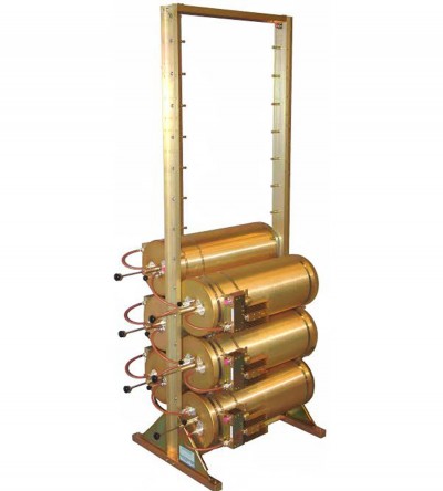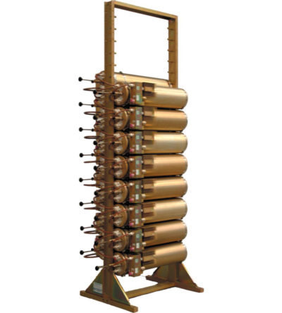
- Can easily support 250 kHz Tx-Tx spacing
- Flexible design: from 1-21 channel capacity
- Expandable: 1 or more additional channels at a time; re-configurable equipment
- 746-1000 MHz, 254 MHz of operating bandwidth
- Temperature compensation to ensure frequency stability
- High attenuation to minimize desense and interference
- Ultra-low insertion losses; low coupling and bridging losses
- Continuous high-power handling capability; 150 watts – 24/7
-
 Incorporates expandability, close frequency spacing and some of the lowest insertion losses in the industry
 -
Incorporates expandability, close frequency spacing and some of the lowest insertion losses in the industry
- Can easily support 125 kHz Tx-Tx spacing or 75 kHz spacing while using 10” cavities
- Flexible design: from 1-21 channel capacity
- Expandable: 1 or more additional channels at a time; re-configurable equipment
- 380-512 MHz, 132 MHz of operating bandwidth
- Temperature compensation to ensure frequency stability
- High attenuation to minimize desense and interference
- Ultra-low insertion losses; low coupling and bridging losses
- Continuous high-power handling capability; 150 watts – 24/7
-
Incorporates expandability, close frequency spacing and some of the lowest insertion losses in the industry
- Can easily support 100 kHz Tx-Tx spacing or 75 kHz spacing while using 10” cavities
- Flexible design: from 1-21 channel capacity
- Expandable: 1 or more additional channels at a time; re-configurable equipment
- 215-300 MHz, 85 MHz of operating bandwidth
- Temperature compensation to ensure frequency stability
- High attenuation to minimize desense and interference
- Ultra-low insertion losses; low coupling and bridging losses
- Continuous high-power handling capability; 150 watts – 24/7
-
Incorporates expandability, close frequency spacing and some of the lowest insertion losses in the industry
- Can easily support 75 kHz Tx-Tx spacing or 50 kHz spacing while using 10” cavities
- Flexible design: from 1-21 channel capacity
- Expandable: 1 or more additional channels at a time; re-configurable equipment
- 132-174 MHz, 42 MHz of operating bandwidth
- Temperature compensation to ensure frequency stability
- High attenuation to minimize desense and interference
- Ultra-low insertion losses; low coupling and bridging losses
- Continuous high-power handling capability; 150 watts – 24/7
-
Incorporates expandability, close frequency spacing and some of the lowest insertion losses in the industry
- Can easily support 75 kHz Tx-Tx spacing or 50 kHz spacing while using 10” cavities
- Flexible design: from 1-21 channel capacity
- Expandable: 1 or more additional channels at a time; re-configurable equipment
- 108-136 MHz, 28 MHz of operating bandwidth
- Temperature compensation to ensure frequency stability
- High attenuation to minimize desense and interference
- Ultra-low insertion losses; low coupling and bridging losses
- Continuous high-power handling capability; 150 watts – 24/7
-
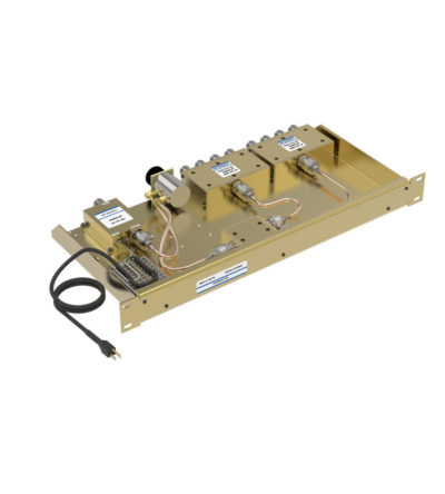
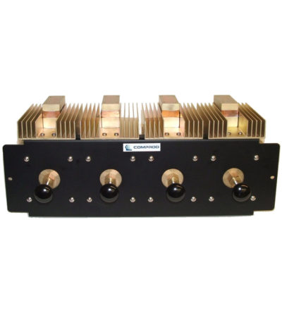
Ideal for combining multiple Rx frequencies onto the same antenna
- Available in 2, 4, 8, 12, 16 and 32
- Simple and cost-effective design
- Standard 19” Rack Mount (RM) or cavity-mounted (CM) versions
- Each unit consists of a power splitter and an RF amplifier.
- Plug-in Power Supply (PS) optional
-
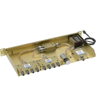
Ideal for combining multiple Rx frequencies onto the same antenna
- Available in 2, 4, 8, 12 , 16 and 32 port configurations
- Simple and cost-effective design
- Standard 19” Rack Mount (RM) or cavity-mounted (CM) versions
- Each unit consists of a power splitter and an RF amplifier.
- Plug-in Power Supply (PS) optional
-
Ideal for combining multiple Rx frequencies onto the same antenna
- Available in 2, 4, 8, 12, 16 and 32 port configurations
- Simple and cost-effective design
- Standard 19” Rack Mount (RM) or cavity-mounted (CM) versions
- Each unit consists of a power splitter and an RF amplifier.
- Plug-in Power Supply (PS) optional
-
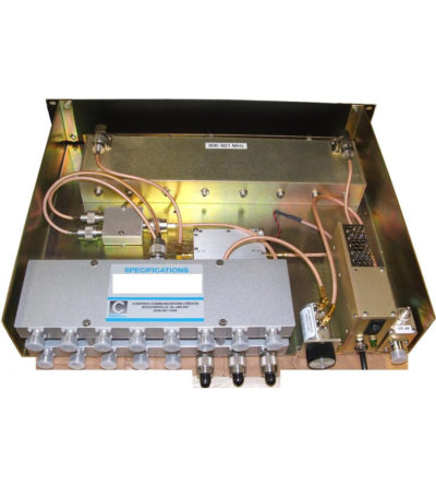
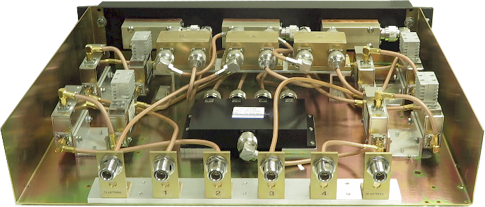
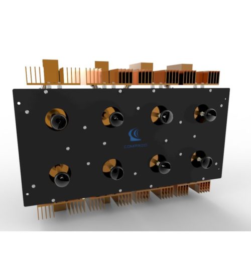
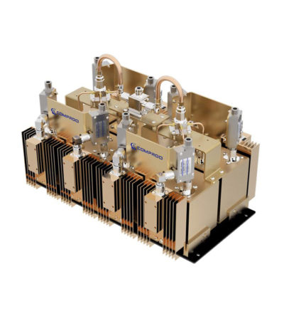
Combines multiple receiver frequencies onto the same antenna
- A low noise amplifier provides gain across the frequency band
- Low noise figure and low intermodulation generation
- Features up to 16 ports (24 and 32 port versions are available)
- -30 dB signal sampler port that can also be used to inject a signal
-
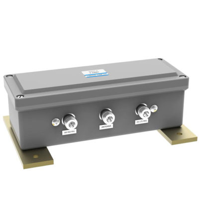
Designed for easy installation, reducing coaxial runs, and in-building applications with multi-band antennas
- Allows multiple bands to share the same transmission lines
- Available in VHF, UHF and 800/900 MHz bands
- Can be Tower-Mounted (TM), Rack-Mounted (RM) or stand alone
-
Designed for easy installation, reducing coaxial runs, and in-building applications with multi-band antennas
- Allows multiple bands to share the same transmission lines
- Available in VHF, UHF and 800/900 MHz bands
- Can be Tower-Mounted (TM), Rack-Mounted (RM) or stand alone
-
Fully expandable and reconfigurable
- Features X-Pass, plug-and-play technology
- Designed to offer engineers and technicians many options when designing or upgrading a site
-
Dielectric resonator technology resulting in higher performance than standard RF cavities in a much smaller package
- Available for the 764-776, 851-869 and 935-941 MHz bands
- Designed for tight channel spacing
- Lowest insertion loss, high isolation for maximum coverage and reduced interference
- Easy field expandability with X-Pass technology - one channel at a time
- Compact, robust design for rapid installations, increased mobility and ease of maintenance
-
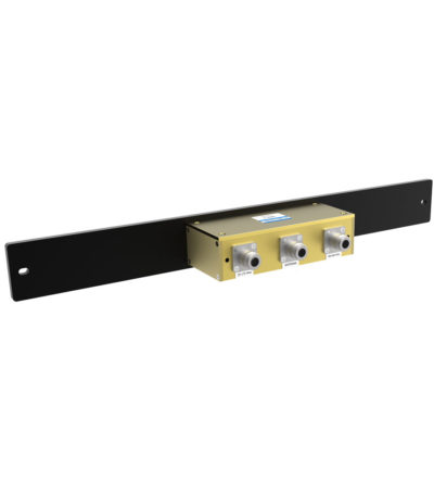
Our Control Station Combiners (CSC) is an ideal solution to reduce the number of antennas required on a communications site by maintaining a high radio-to-radio isolation at all times. It can significantly reduce tower clutter and loading, and simplify cabling installation at control center facilities. This product provides frequency-agile operation across a frequency range from 136 up to 174 MHz. This combiner has the possibilities to be connected to two antennas TX and RX. In case of only one antenna is used for TX and RX, an external duplexer is required. DOWNLOAD PDF
-
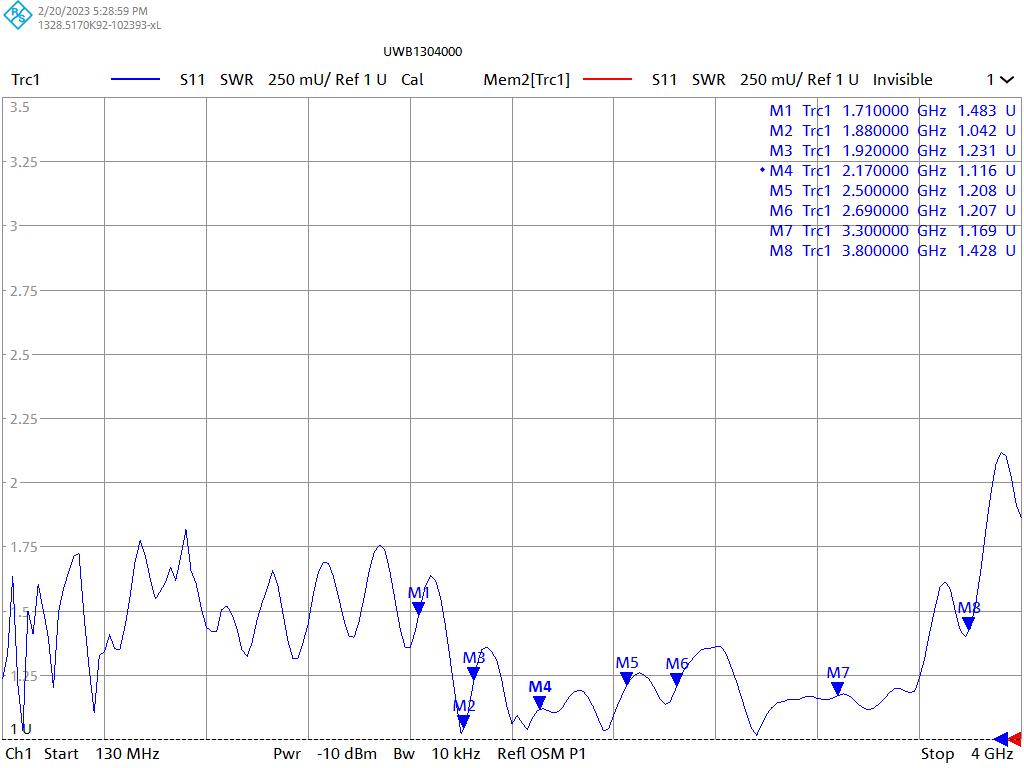
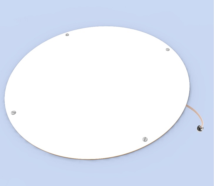
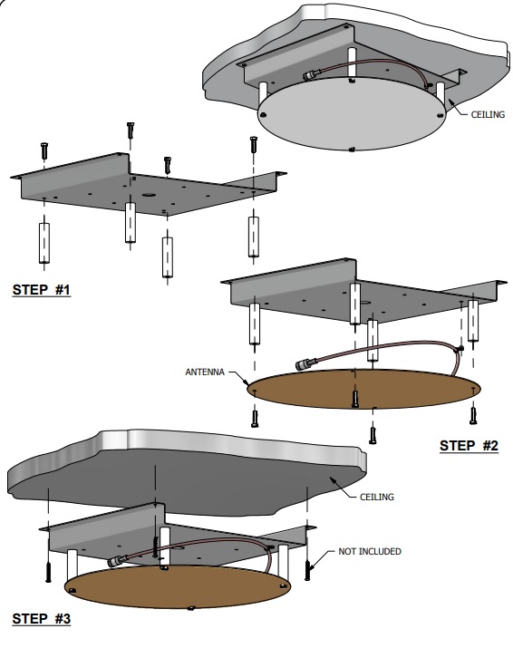
Usage for Distributed Antenna Systems (DAS) for Public Safety or LTE communication in multiple stories of a building.
- Mounting on a ceiling or gyprock wall, without need of a ground plane
-
Produc short description before changes Usage for Distributed Antenna Systems (DAS) for Public Safety or LTE communication in multiple stories of a building. The antenna’s main application includes usage for:
- Distributed Antenna Systems (DAS) for Public Safety
- LTE communication
- Cellular bands in multiple stories of a building
- Mounting on a ceiling or gyprock wall, without need of a ground plane
-
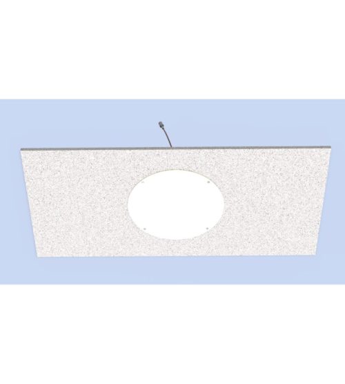
Usage for Distributed Antenna Systems (DAS) for Public Safety or LTE communication in multiple stories of a building.
- Designed to be installed on hard surfaces such as concrete or metal structures.
- A layer of Kydex 6200 of 0.3’’ thickness is added to meet the recommended fire safety practices of both the Federal Transit Administration (FTA) and the Federal Rail Administration (FRA) for smoke emission and flammability as tested under ASTM E-662 and ASTM E-162
-
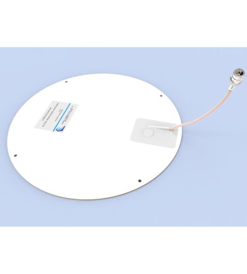
Usage for Distributed Antenna Systems (DAS) for Public Safety or LTE communication in multiple stories of a building.
- Mounting on a ceiling or gyprock wall, without need of a ground plane
- An extra protection can be added to meet the recommended fire safety practices of both the Federal Transit Administration (FTA) and the Federal Rail Administration (FRA) for smoke emission and flammability as tested under ASTM E-662 and ASTM E-162
-
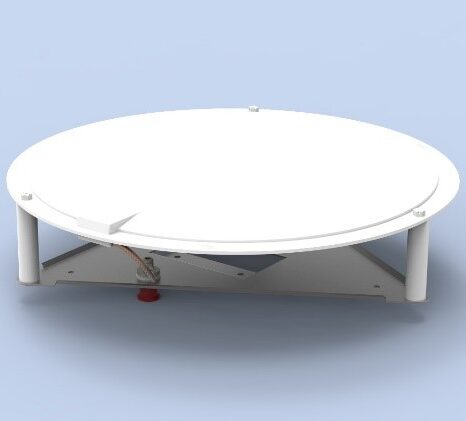
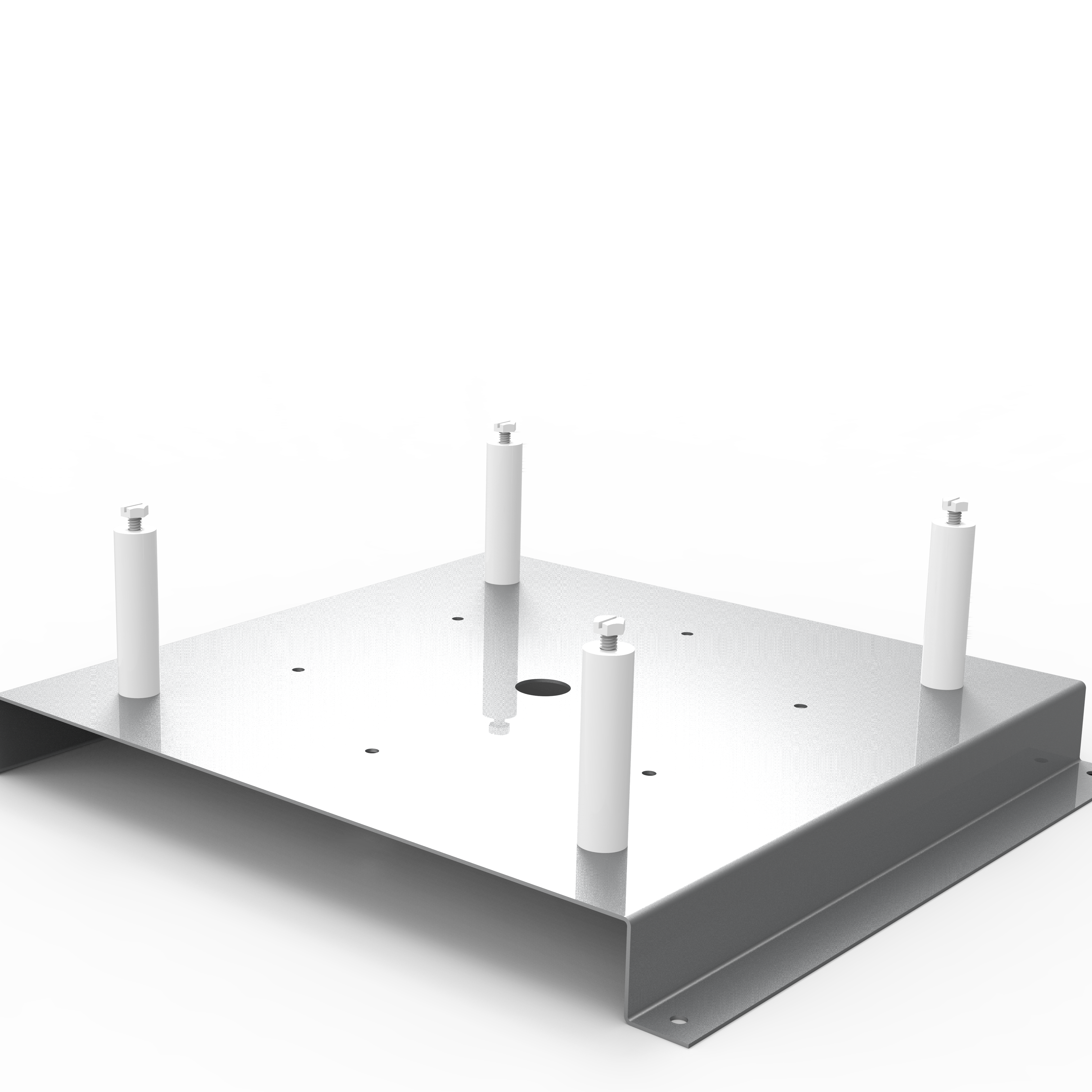
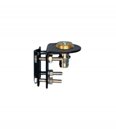
Our new mounting solution UWB-MOUNT-KIT for UWB1301000-NF and UWB1304000-NF has been designed for applications where the antenna will be installed on a surface other than a ceiling or gyprock wall, such as: wood, metal or concrete. DOWNLOAD PDF
-
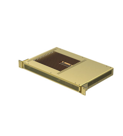
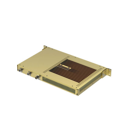
This compact unidirectional (1 way) RF over Fiber (RFoF) transmitter is designed for conversion of RF signals to optical signals carried over long distances. The Tx unit using an optical transmitter, converts RF to Optical signal and the Rx unit converts back to RF signal. The two units are connected through customer’s single mode fiber.
- Noise Figure 6 dB with LNA with MDS ~-168 dB/Hz for very low incoming signals
- Impedance of 50 Ohm and 75 Ohm
- Gain variation S21 (fo) of ±1 dB for 90° C variation
- Better linearity,
- Excellent gain flatness
- Tx, Rx and Link gain control
- Real-time diagnostic of deployed links through GUI installed on the PC
-
Our Control Station Combiners (CSC) is an ideal solution to reduce the number of antennas required on a communications site by maintaining a high radio-to-radio isolation at all times. It can significantly reduce tower clutter and loading, and simplify cabling installation at control center facilities. This product provides frequency-agile operation across a frequency range from 380 up to 512 MHz. This combiner has the possibilities to be connected to two antennas TX and RX. In case of only one antenna is used for TX and RX, an external duplexer is required. DOWNLOAD PDF
-
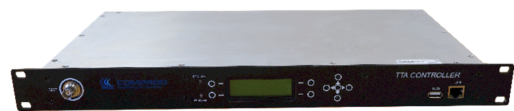
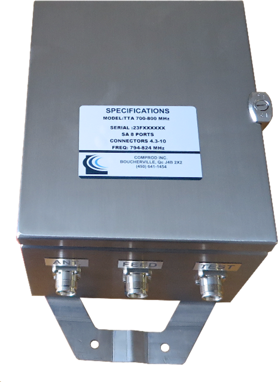
Top-Tower Amplifier Our modular Tower-Top Amplifier (TTA) systems provide superior receiver system performance and excellent electrical reliability by improving base station Up Link (UL) sensitivity. TTA systems overcome link budget imbalance between the Up Link and Down Link (DL) by boosting received signal to overcome received path loss (feeder losses).
- Improved base station UL sensitivity
- Redundant LNA with automatic change over
- LNA bypass modes
- Monitoring & Control via GUI
- SNMP Alarms
- Remote Access
-
Dielectric resonator technology resulting in higher performance than standard RF cavities in a much smaller package
- Available for the 764-776, 851-869 and 935-941 MHz bands
- Designed for tight channel spacing
- Lowest insertion loss, high isolation for maximum coverage and reduced interference
- Star configuration
- Compact, robust design for rapid installations, increased mobility and ease of maintenance
-
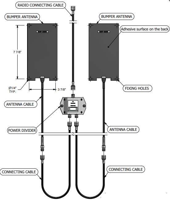
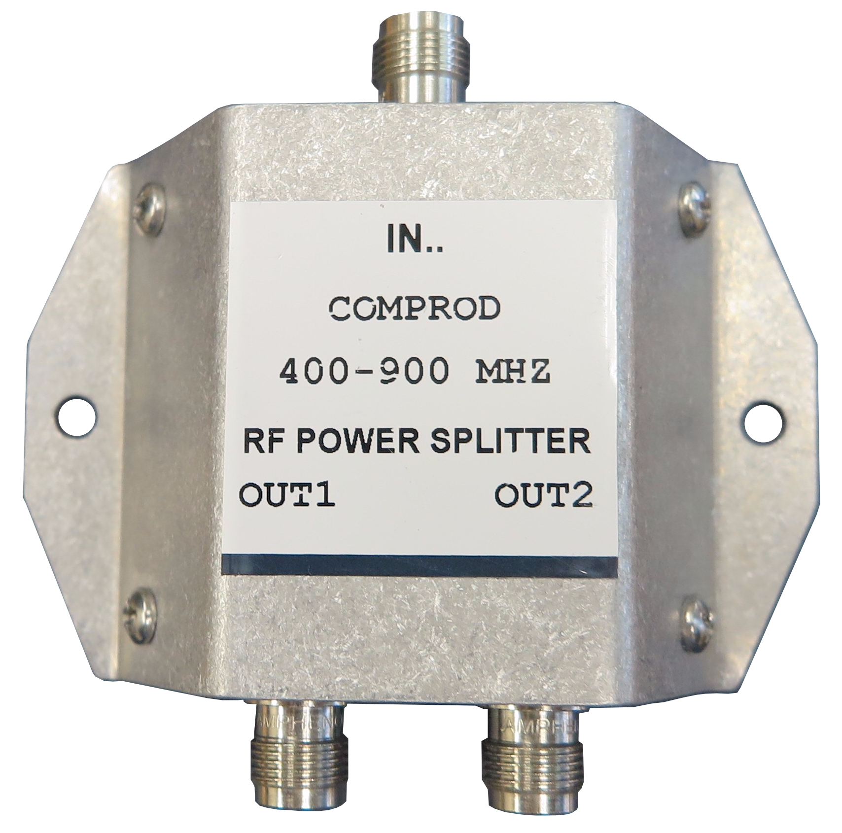
For optimal performance two bumper antennas are installed in a vehicle: one at the front of the vehicle and one at the rear. The Comprod power splitter (SPLT-BUMP-400900) is designed to help to create an omnidirectional pattern around the vehicle and enable better network coverage. DOWNLOAD PDF
-
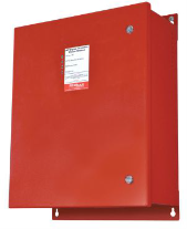
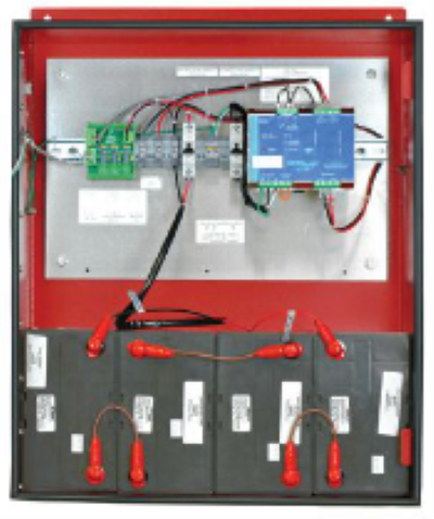
PE-48V-480W-55AH-UL: Battery backup system compatible with our VHF/UHF BDA and any other 48V BDA. Features
- Certified to UL 924
- AC input: 115/230 VAC (factory wired for 120 V AC)
- Input protection: AC breaker
- Load protection: DC breaker
- Typical dimensions (H x W x D): 30” x 23” x 10.5”
- Shipping Weight: 114 lbs for 24V system, 230 lbs for 48 V system
- Batteries Included: maintenance free, valve regulated, sealed lead acid 55 AH capacity
- NFPA compliant Dry Contact Alarms for the following conditions:
- Charger Failure
- Battery Discharged to 30 % of capacity.
- AC Power or Rectifier failure
-
PE-24V-240W-55AH-UL: Battery backup system compatible with our VHF/UHF BDA and any other 24V BDA. Features
- Certified to UL 924
- AC input: 115/230 VAC (factory wired for 120 V AC)
- Input protection: AC breaker
- Load protection: DC breaker
- Typical dimensions (H x W x D): 30” x 23” x 10.5”
- Shipping Weight: 114 lbs for 24V system, 230 lbs for 48 V system
- Batteries Included: maintenance free, valve regulated, sealed lead acid 55 AH capacity
- NFPA compliant Dry Contact Alarms for the following conditions:
- Charger Failure
- Battery Discharged to 30 % of capacity.
- AC Power or Rectifier failure
-
CABLE KITS: Comprod’s brass mounts and cable kits are among the best in the Industry. The cable kits present a consistent 50 Ohms impedance to match our mobile antennas, ensuring that our customers receive the best combined performance from the antennas and the cable kits. The quality of our designs is one of the factors that allows our wideband models to outperform the competition. CONNECTORS: We carry and stock a complete line of connectors. Please contact us for additional information. DOWNLOAD PDF
-
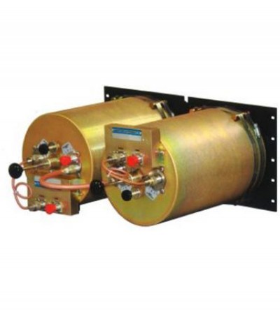
Designed for compact, close frequency installations. Ideal for very closely spaced frequency transmitters
- High isolation: minimizes intermodulation products
- Low loss: maximizes system performance
- Continuous power:
- Physical size and materials used maximizes the performance across the operating band
-
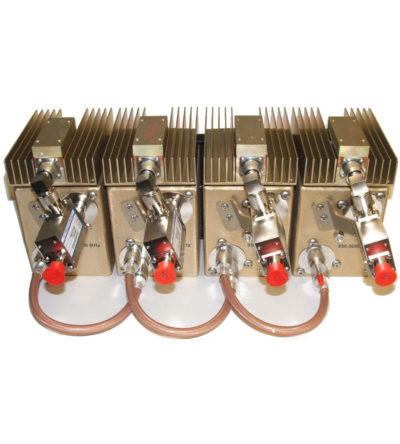
Designed for compact, close frequency installations. Ideal for very closely spaced frequency transmitters
- Ideal for intermodulation panels, providing extra protection with their second harmonic filters, when physical space is at a premium or is constrained, and for providing extra isolation between two very close transmitters
- High isolation: minimizes intermodulation products
- Low loss: maximizes system performance
- Continuous power:
- Physical size and materials used maximizes the performance across the operating band
-
Designed for compact, close frequency installations. Ideal for very closely spaced frequency transmitters
- Ideal for intermodulation panels, providing extra protection with their second harmonic filters, when physical space is at a premium or is constrained, and for providing extra isolation between two very close transmitters
- High isolation: minimizes intermodulation products
- Low loss: maximizes system performance
- Continuous power:
- Physical size and materials used maximizes the performance across the operating band