132-174 MHz

  • Circular Polarized Antenna
    205-70

    Frequency Range: 138-174, 406-512, 764-806, 806-866, 900-960 MHz
    Gain: Unity
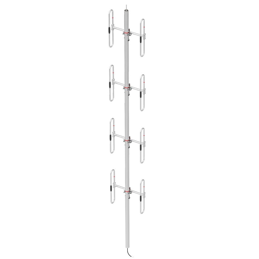
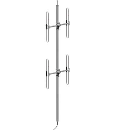
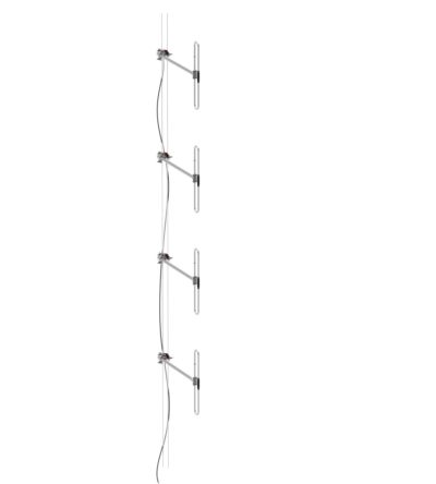
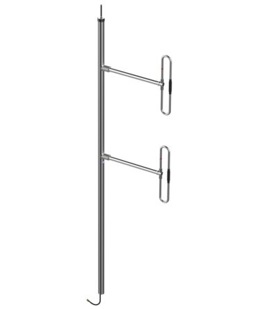
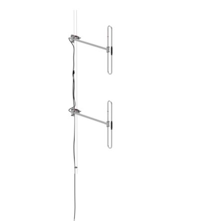
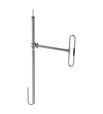
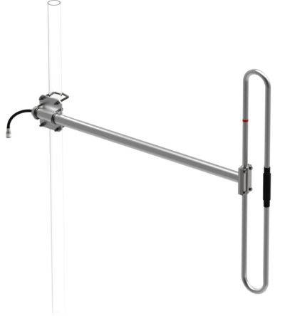
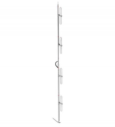
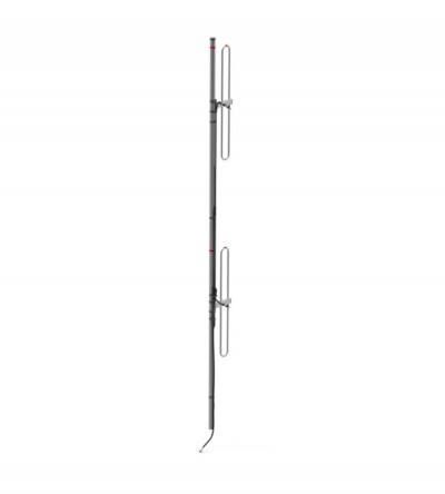
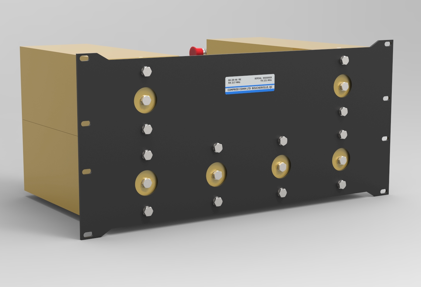
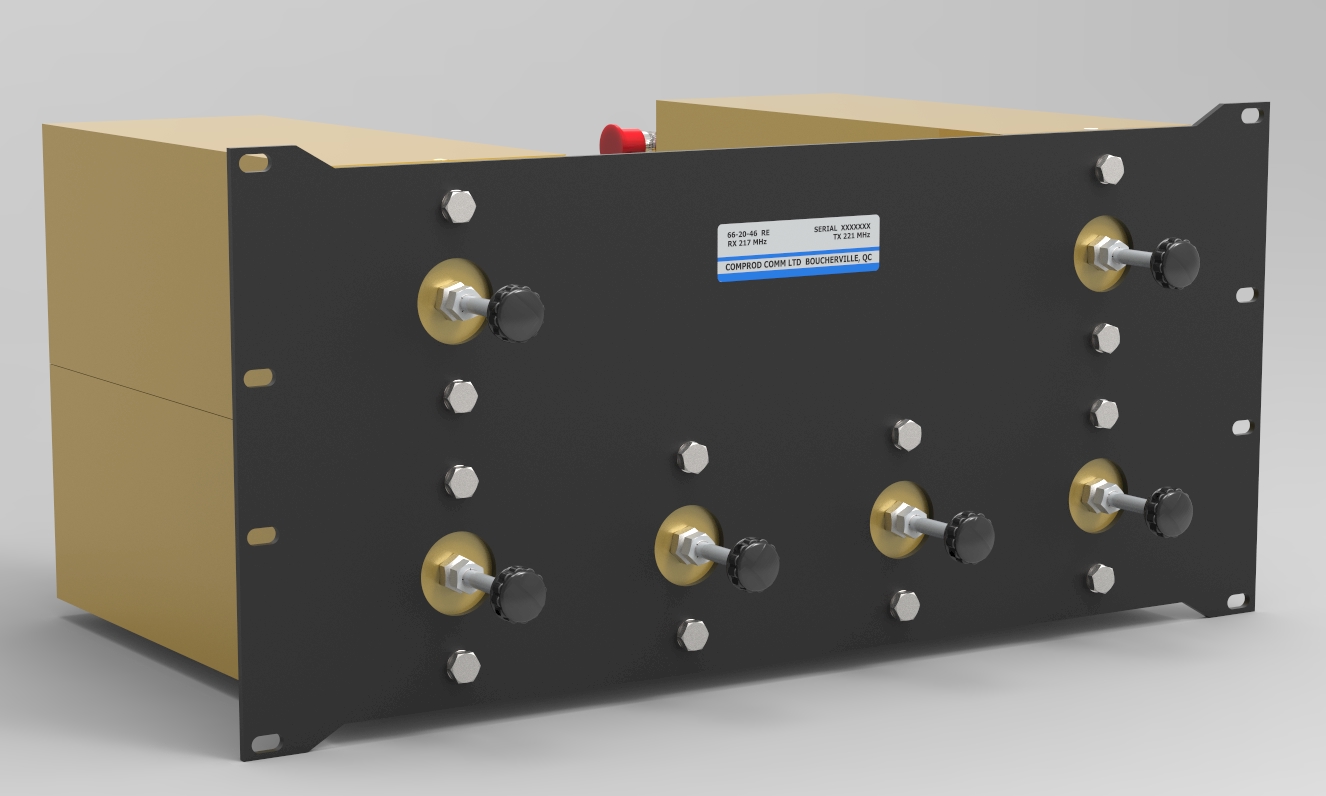
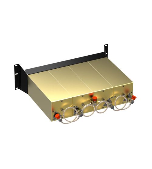
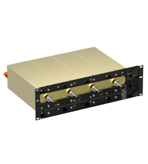
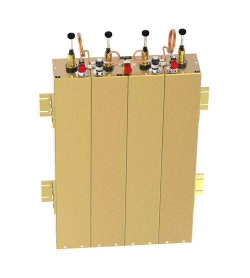
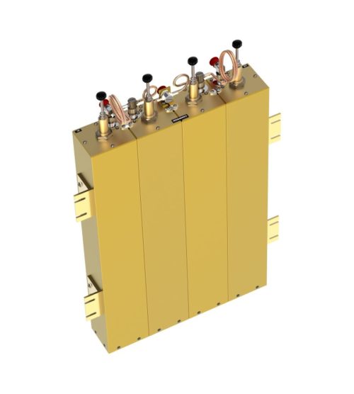
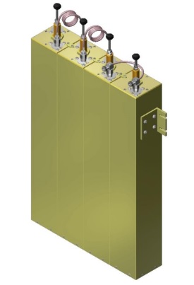
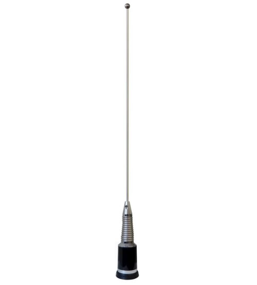
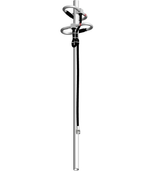
    Constructed from high strength, corrosion resistant aluminum alloy and stainless steel
    • Available in VHF, UHF, 800/900 MHz configurations
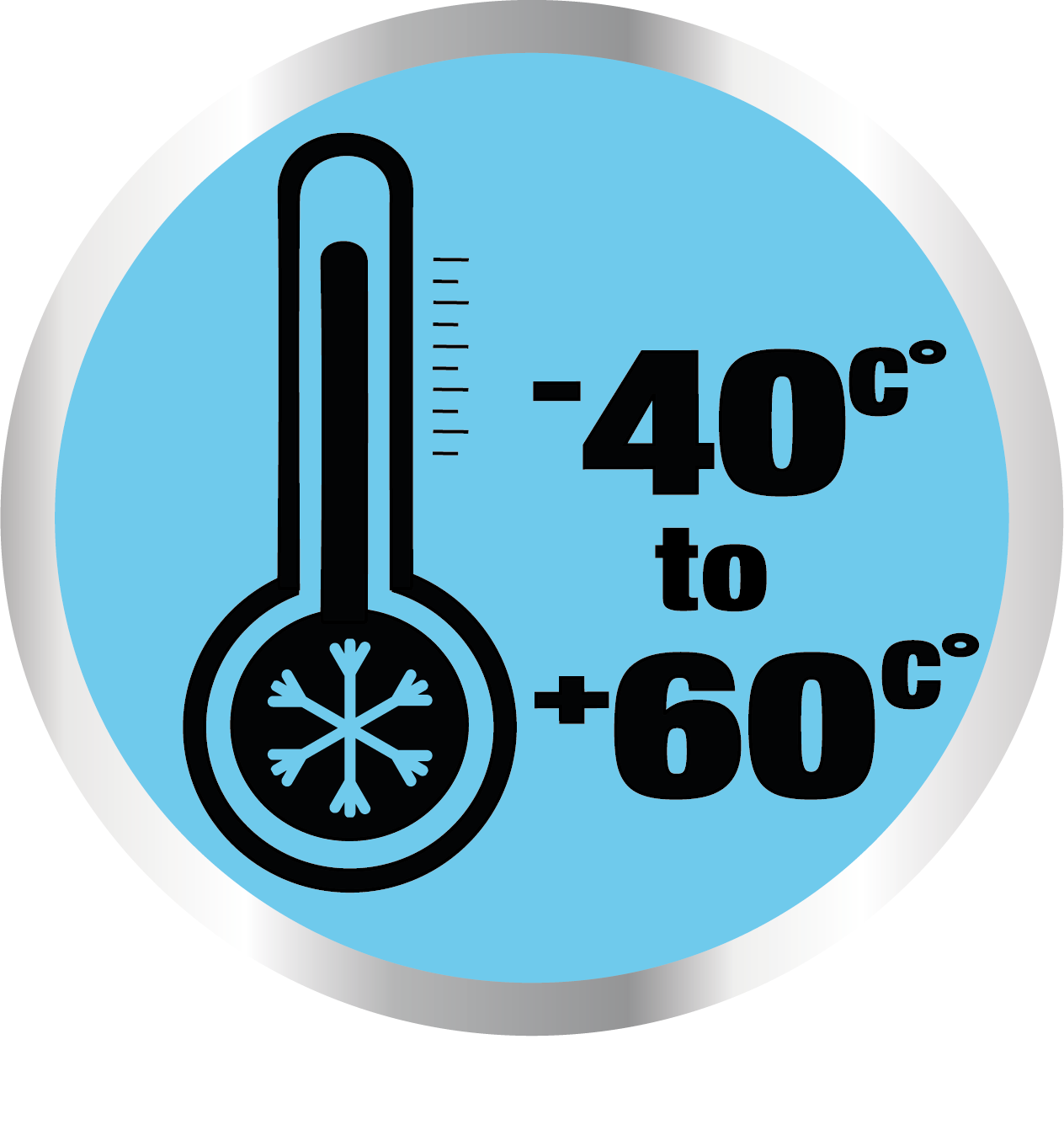
    • Rugged design to withstand harsh environmental conditions
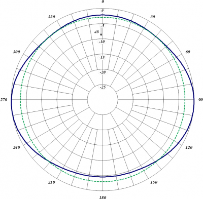
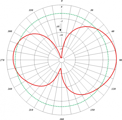
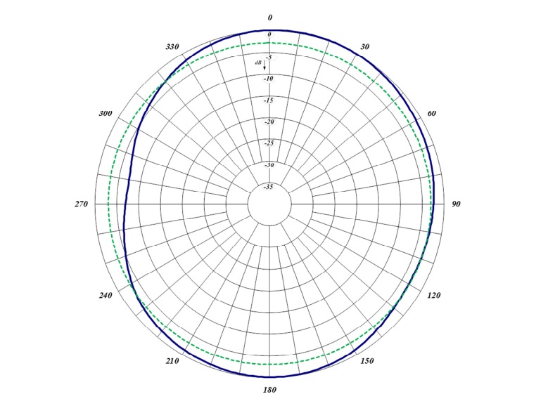
    • Circular polarization
    • DC ground for lightning protection
    This antennas are available in both Right Hand Circular Polarization (RHCP) and Left Hand Circular Polarization (LHCP). SPEC SHEET VHF SPEC SHEET UHF SPEC SHEET 700/800/900
  • BDA 806870 Bi-Directional Amplifier (Signal Booster)
    Designed and engineered to meet the fire protection codes (NFPA and IFC standards). Please, note that BDA380512 is a generic number. Actual order number will be assigned to a system design. Specific frequencies are required for this product design.
    • Rack mounted or in NEMA 4/4x waterproof, stainless steel enclosures
    • Low noise figure, wide dynamic range
    • Visual alarms and remote failure monitoring with Graphical User Interface
    • FCC and IC certified
      • FCC ID: WDM-BDA380512
      • IC: 7755A-BDA380512
    This product is available in UDA version as well. DOWNLOAD PDF DOWNLOAD MANUALS
  • BDA 806870 Bi-Directional Amplifier (Signal Booster)
    Designed and engineered to meet the fire protection codes (NFPA and IFC standards). Please, note that BDA138174 is a generic number. Actual order number will be assigned to a system design. Specific frequencies are required for this product design.
    • Rack mounted or in NEMA 4/4x waterproof, stainless steel enclosures
    • Low noise figure, wide dynamic range
    • Visual alarms and remote failure monitoring with Graphical User Interface
    • FCC and IC certified
      • FCC ID: WDM-BDA138174
      • IC: 7755A-BDA138174
    This product is available in UDA version as well. DOWNLOAD PDF DOWNLOAD MANUALS
  • 884-70 VHF Exposed Dipole Array

    Frequency Range: 138-174 MHz
    Gain: 6.0/8.5 dBd
    Offered in Omnidirectional or Bi-directional versions
    • Internal cabling, fixed dipole-mast spacing and adjustable pattern control
    • Heavy-duty, black anodized  and top mount only versions available
    DOWNLOAD PDF DOWNLOAD DIGITAL PATTERNS
  • 882-70 VHF Exposed Dipole Array

    Frequency Range: 138-174 MHz
    Gain: 3.0/5.5 dBd
    Offered in omnidirectional or bi-directional versions
    • Internal cabling, fixed dipole-mast spacing and adjustable pattern control
    • Heavy-duty, black anodized  and top mount only versions available
    DOWNLOAD PDF DOWNLOAD DIGITAL PATTERNS
  • 876-70 Dual Exposed Dipole Array

    876F-70 Dual Exposed Dipole Array

    Frequency Range: 138-174 MHz
    Gain: 5.0-5.5 dBd
    Ideal for applications where costs are calculated per antenna
    • Available in many configurations
    • VHF, UHF or 700/800/900 MHz antennas can be combined onto one mast
    • Mix and match with our 770, 790, 840, 870 and 880 series antennas
    • Can be configured for side or top mount
    • Low VSWR version with maximum gain over specified frequency
    • Certain versions of antennas have an adjustable pattern for 3 dBd omnidirectional or 6 dBd offset coverage
    • Heavy-duty versions available
    DOWNLOAD PDF DOWNLOAD DIGITAL PATTERNS
  • 874F-70 VHF Exposed Dipole

    874F-70 VHF Exposed Dipole

    Frequency Range: 138-174 MHz
    Gain: 8.0-8.5 dBd
    Adjustable, fixed, side or top mount antenna
    • Offered in a 1/4, 3/8 or 1/2 wave spacing version
    • The 874A-70 has external cabling and a field-adjustable pattern.
    • The 874F-70 has internal cabling and fixed dipole-mast spacing.
    • Heavy-duty and black anodized versions available
    DOWNLOAD PDF DOWNLOAD DIGITAL PATTERNS
  • 874-70-LM VHF Exposed Dipole (Without Mast)

    Frequency Range: 138-174 MHz
    Gain: 8.0-8.5 dBd
    Adjustable-only, side mount or top mount antenna
    • External cabling and field adjustable pattern
    • Heavy-duty and black anodized versions available
    DOWNLOAD PDF DOWNLOAD DIGITAL PATTERNS
  • 872F-70 VHF Exposed Dipole

    Frequency Range: 138-174 MHz
    Gain: 5.0-5.5 dBd
    Adjustable, fixed, side or top mount antenna
    • Offered in a 1/4, 3/8 or 1/2 wave spacing version
    • The 872A-70 has external cabling and a field-adjustable pattern.
    • The 872F-70 has internal cabling and fixed dipole-mast spacing.
    • Heavy-duty and black anodized versions available
    DOWNLOAD PDF DOWNLOAD DIGITAL PATTERNS
  • 872-70-LM VHF Exposed Dipole (Without Mast)

    Frequency Range: 138-174 MHz
    Gain: 5.0-5.5 dBd
    Adjustable-only, side mount or top mount antenna
    • External cabling and field adjustable pattern
    • Heavy-duty and black anodized versions available
    DOWNLOAD PDF DOWNLOAD DIGITAL PATTERNS
  • 871F-70 VHF Exposed Dipole

    871F-70 VHF Exposed Dipole

    Frequency Range: 138-174 MHz
    Gain: 2.0-2.5 dBd
    Adjustable, fixed, side or top mount antenna
    • Offered in a 1/4, 3/8 or 1/2 wave spacing version
    • The 871A-70 has external cabling and a field-adjustable pattern.
    • The 871F-70 has internal cabling and fixed dipole-mast spacing.
    • Heavy-duty and black anodized versions available
      DOWNLOAD PDF DOWNLOAD DIGITAL PATTERNS
  • 871-70-LM VHF Exposed Dipole (Without Mast)

    Frequency Range: 138-174 MHz
    Gain: 2.0-2.5 dBd
    Adjustable-only, side mount or top mount antenna
    • External cabling and field adjustable pattern
    • Heavy-duty and black anodized versions available
    DOWNLOAD PDF DOWNLOAD DIGITAL PATTERNS
  • 834-70 Light Duty VHF Exposed Dipole

    Frequency Range: 148-174 MHz
    Gain: 6.0 or 9.0 dBd
    Light duty VHF exposed dipole
    • Available in a VHF configuration (2 frequency splits)
    • Low VSWR version with maximum gain over specified frequency
    • External cabling and fixed dipole-mast spacing
    • Adjustable pattern for omnidirectional or offset coverage
    • The 834-70 antenna is shipped in two sections to be assembled on site.
      DOWNLOAD PDF
  • 832-70 Light Duty VHF Exposed Dipole

    Frequency Range: 148-174 MHz
    Gain: 3.0 or 6.0 dBd
    Light duty VHF exposed dipole
    • Available in a VHF configuration (2 frequency splits)
    • Low VSWR version with maximum gain over specified frequency
    • External cabling and fixed dipole-mast spacing
    • Adjustable pattern for omnidirectional or offset coverage
    DOWNLOAD PDF  
  • 68-13-71 X-Pass Cavity

    Frequency Range: 136-174 MHz
    Designed for flexible, close frequency systems
    • Each cavity has both a Reject and a Pass band curve
    • Available in single units, they can be combined with band pass, notch, and pass reject cavities for added protection and isolation
    • Temperature compensated to ensure frequency stability
    • High attenuation to minimize desense and interference from adjacent systems
    • Adjustable loops: each cavity has a calibration index for easy field tuning
    DOWNLOAD PDF
  • 66-13-76 Pseudo Band Pass Duplexer

    Frequency Range: 138-174 MHz
    Designed for quick and easy installations
    • Designed for the combination of two frequencies requiring extra isolation. Can also be used as efficient pre-selectors
    • Available in 4 or 6 cavity configurations
    • Temperature compensated to ensure frequency stability
    • High attenuation to minimize desense and interference from adjacent systems
    • Adjustable loops: each cavity has a calibration index for easy field tuning
    DOWNLOAD PDF
  • 66-13-74 Pseudo Band Pass Duplexer

    Frequency Range: 138-174 MHz
    Designed for quick and easy installations
    • Designed for the combination of two frequencies requiring extra isolation. Can also be used as efficient pre-selectors
    • Available in 4 or 6 cavity configurations
    • Temperature compensated to ensure frequency stability
    • High attenuation to minimize desense and interference from adjacent systems
    • Adjustable loops: each cavity has a calibration index for easy field tuning
    DOWNLOAD PDF
  • Ideal for compact high performance applications
    • Designed for the combination of two frequencies that require extra isolation. Can also be used as efficient pre-selectors
    • An eight cavity configuration is also available for a higher level of isolation and selectivity
    • Can be retuned in the field
    DOWNLOAD PDF
  • 66-13-46 (6) 4-inch Cavity Duplexer

    Frequency Range: 138-174 MHz
    Ideal for high power, close frequency separation installations
    • Designed for combining two frequencies that require extra isolation. Can also be used as efficient pre-selectors
    • Temperature compensated to ensure frequency stability
    • High attenuation to minimize desense and interference from adjacent systems
    • Adjustable loops
    DOWNLOAD PDF
  • Ideal for compact high performance applications
    • Designed for the combination of two frequencies that require extra isolation. Can also be used as efficient pre-selectors
    • A six and an eight cavity configuration is also available for a higher level of isolation and selectivity
    • Can be retuned in the field
    DOWNLOAD PDF
  • 66-13-44 (4) 4-inch Cavity Duplexer

    Frequency Range: 138-174 MHz
    Ideal for high power, close frequency separation installations
    • Designed for combining two frequencies that require extra isolation. Can also be used as efficient pre-selectors
    • Temperature compensated to ensure frequency stability
    • High attenuation to minimize desense and interference from adjacent systems
    • Adjustable loops
    DOWNLOAD PDF
  • 63-13-71 Notch Cavity

    Frequency Range: 136-174 MHz
    Designed to reject one narrow band of frequencies, while letting all others pass in the operating band
    • Can be cascaded or added to one another in order to sharpen the attenuation of the rejection curve
    • Temperature compensated to ensure frequency stability
    • High attenuation to minimize desense and interference from adjacent systems
    • Adjustable loops: each cavity has a calibration index
    DOWNLOAD PDF  
  • 62-13-71 Pass-Reject Cavity

    Frequency Range: 136-174 MHz
    Designed to pass a frequency band and reject a narrow band of frequencies
    • Can reject frequencies on either the high or low side of the pass frequency
    • Temperature compensated to ensure frequency stability
    • High attenuation to minimize desense and interference
    DOWNLOAD PDF  
  • 61-13-71 Band Pass Cavity

    Frequency Range: 136-174 MHz
    Designed to minimize interference from adjacent channels and outside systems
    • Available in single, dual or triple units
    • Temperature compensated to ensure frequency stability
    • High attenuation
    • Adjustable loops: each cavity has a calibration index to reference insertion loss
    DOWNLOAD PDF  
  • 60-38-43 XMF Band Pass UHF Multicoupler

    Frequency Range: 380-512 MHz
    Designed for minimizing interference from adjacent channels and outside systems
    • Available in single, dual, triple or additional units
    • Temperature compensated to ensure frequency stability
    • High attenuation to minimize desense and interference from adjacent systems
    • Adjustable loops: each cavity has a calibration index for easy field tuning
    DOWNLOAD PDF
  • 60-13-73 XMF Band Pass VHF Multicoupler

    Frequency Range: 138-174 MHz
    Designed for minimizing interference from adjacent channels and outside systems
    • Available in single, dual, triple or additional units
    • Temperature compensated to ensure frequency stability
    • High attenuation to minimize desense and interference from adjacent systems
    • Adjustable loops: each cavity has a calibration index for easy field tuning
    DOWNLOAD PDF
  • 60-13-72 XMF Band Pass VHF Multicoupler

    Frequency Range: 138-174 MHz
    Designed for minimizing interference from adjacent channels and outside systems
    • Available in single, dual, triple or additional units
    • Temperature compensated to ensure frequency stability
    • High attenuation to minimize desense and interference from adjacent systems
    • Adjustable loops: each cavity has a calibration index for easy field tuning
    DOWNLOAD PDF
  • 60-13-71 XMF Band Pass VHF Multicoupler

    Frequency Range: 138-174 MHz
    Designed for minimizing interference from adjacent channels and outside systems
    • Available in single, dual, triple or additional units
    • Temperature compensated to ensure frequency stability
    • High attenuation to minimize desense and interference from adjacent systems
    • Adjustable loops: each cavity has a calibration index for easy field tuning
    DOWNLOAD PDF  
  • 60-13-43 XMF Band Pass VHF Multicoupler

    Frequency Range: 138-174 MHz
    Designed for minimizing interference from adjacent channels and outside systems
    • Available in single, dual, triple or additional units
    • Temperature compensated to ensure frequency stability
    • High attenuation to minimize desense and interference from adjacent systems
    • Adjustable loops: each cavity has a calibration index for easy field tuning
    DOWNLOAD PDF
  • 580-75 VHF Antenna

    Frequency Range: 132-174 MHz
    Gain: 3 dBd
    • 3.0 dBd gain achieved by featuring a 5/8-wave whip with a base loaded matching coil
    • Manufactured using the best corrosion-resistant materials and finishes available
    • Triple-plated chrome brass with a large insert molded low-loss coil form and spring-loaded, gold-plated contact
    • O-ring seals and overlap construction to ensure a moisture-proof installation
    • Standard Motorola NMO type mount
    DOWNLOAD PDF
  • 578-75 VHF Wideband Antenna

    Frequency Range: 138-174 MHz
    Gain: 2 dBd
    • 2.0 dBd of gain over its operating bandwidth
    • Manufactured using the best corrosion-resistant materials and finishes available
    • Triple-plated chrome brass with a large insert molded low-loss coil form and spring-loaded, gold-plated contact
    • Rubber boot and overlap construction to ensure a moisture-proof installation
    • Standard TAD / NMO type mount
    DOWNLOAD PDF
  • 577-75 VHF Wideband Antenna

    Frequency Range: 136-174 MHz
    Gain: 2 dBd
    No ground plane antenna
    • 2.0 dBd of gain over its operating bandwidth
    • Manufactured using the best corrosion-resistant materials and finishes available
    • Triple-plated chrome brass with a large insert molded low-loss coil form and spring-loaded, gold-plated contact
    • Rubber boot ensures a moisture-proof installation
    • Standard Motorola C, M type mount
    DOWNLOAD PDF
  • 576-75 VHF WIDEBAND ANTENNA

    Frequency Range: 148-174 MHz
    Gain: 2.0 dBd
    Broadband 1/2-wave antenna - no ground plane needed
    • Manufactured using the best corrosion-resistant materials and finishes available
    • Triple-plated chrome brass with a large insert, molded low-loss coil form and spring-loaded gold-plated contact
    • Rubber boot ensures a moisture-proof installation/avoid scratching or rusting of the vehicle
    DOWNLOAD PDF
  • 575-75 VHF WIDEBAND ANTENNA

    Frequency Range: 138-174 MHz
    Gain: 2.0 dBd
    Broadband 1/2-wave antenna - no ground plane needed
    • Manufactured using the best corrosion-resistant materials and finishes available
    • Triple-plated chrome brass with a large insert, molded low-loss coil form and spring-loaded gold-plated contact
    • Rubber boot to ensure a moisture-proof installation/avoid scratching or rusting of the vehicle
    DOWNLOAD PDF
  • 573-75 VHF Wideband Antenna

    Frequency Range: 138-174 MHz
    Gain: Unity
    • Gain of unity over its operating bandwidth
    • Manufactured using the best corrosion-resistant materials and finishes available
    • Triple-plated chrome brass with a large insert molded low-loss coil form and spring-loaded, gold-plated contact
    • Rubber boot  to ensure a moisture-proof installation
    • Standard TAD / NMO type mount
    DOWNLOAD PDF
  • 555-75 Economical Antenna

    Frequency Range: 132-960 MHz
    Gain: Unity
    Unity gain in a wideband design for heavy-duty service
    • Manufactured using the best corrosion-resistant materials and finishes available
    • Ultrasonically-welded brass insert and a gold-plated spring-loaded contact
    • Shipped with a factory tuned whip cut to size based on the customer specified frequency range between 136 MHz and 960 MHz
    • Standard Motorola NMO type mount providing an excellent moisture seal even when the antenna is removed
    DOWNLOAD PDF