-
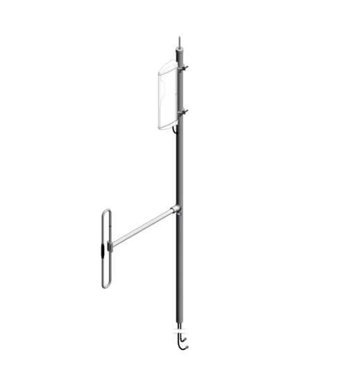
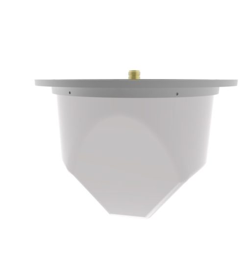
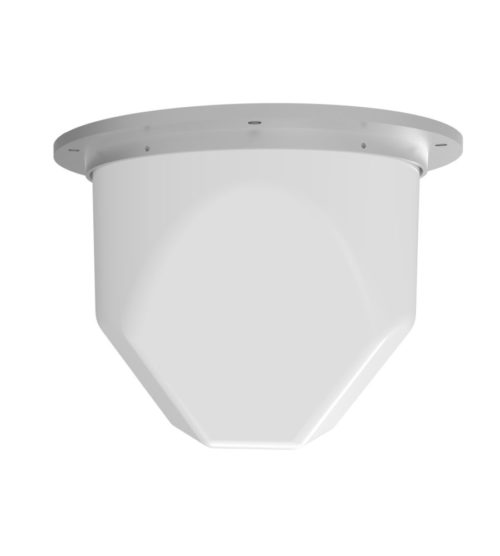
 The F-3980 is a wide band dual antenna with an 871F-70 on the base and a 792-70 on the top. The antenna offers for the 871F-70 a choice of radiation patterns that are determined by the dipole-to-mast spacing. The F-3980 has an internal cabling and is not field adjustable. The 871F-70 antenna is offered in a ¼, 3/8, or ½ wave pattern spacing versions. SPEC Sheet
 -
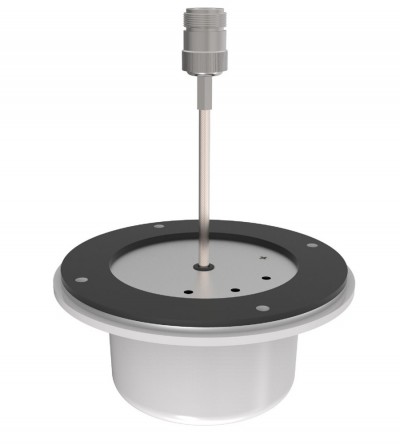
Usage for Distributed Antenna Systems (DAS) for Public Safety or LTE communication in multiple stories of a building.
- Mounting on a ceiling or gyprock wall, without need of a ground plane
- An extra protection can be added to meet the recommended fire safety practices of both the Federal Transit Administration (FTA) and the Federal Rail Administration (FRA) for smoke emission and flammability as tested under ASTM E-662 and ASTM E-162
-
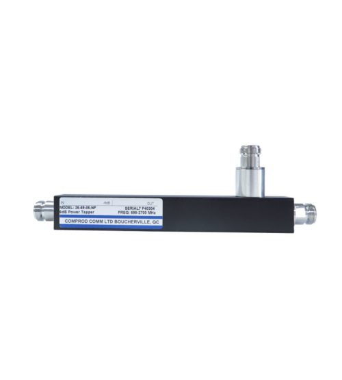
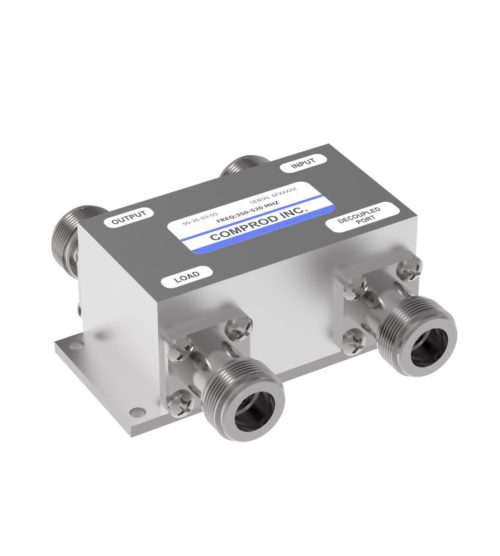
- Low insertion loss
- Lower PIM versions available with DIN 7/16 Connector
- 5 dB values
- Average power of 300 Watts
- Mounting bracket supplied
-
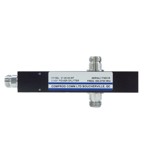
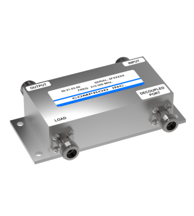
- Low insertion loss
- Lower PIM versions available with DIN 7/16 Connector
- 3 dB values
- Average power of 300 Watts
- Mounting bracket supplied
-
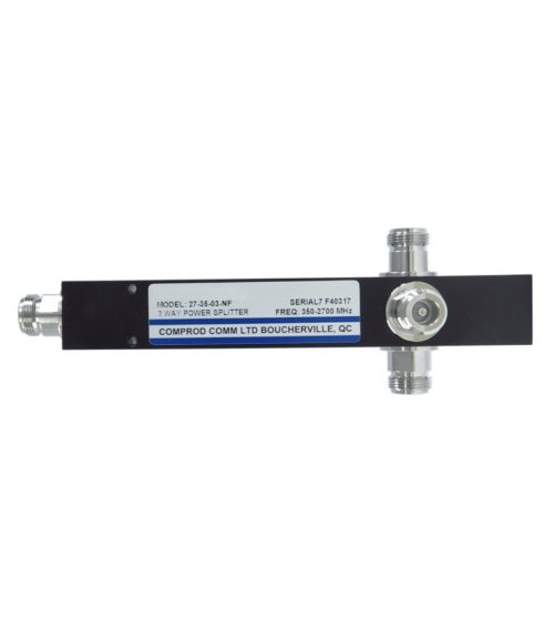
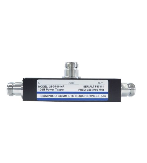
- Low insertion loss
- Lower PIM versions available with DIN 7/16 Connector
- 5, 6, 10, 15, 20, 30 dB values
- Average power of 200 Watts
- Mounting bracket supplied
-
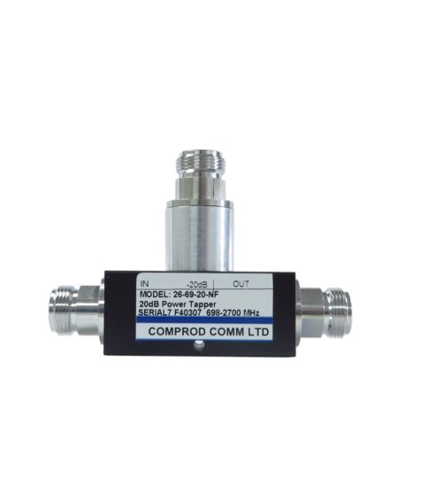
- Low insertion loss
- Lower PIM versions available with DIN 7/16 Connector
- Compact dimensions: 5.5 x 1.0 x 1.7 in.
- 5, 6, 10, 15, 20, 30 dB values
- Average power of 200 Watts
- Mounting bracket supplied
-
Permet la propagation à l’intérieur des bâtiments, de tunnels ou d'environnements publics de radiofréquences externes utilisées à des fins de sécurité publique
- Radôme en Kydex 6200
- Conforme aux normes de sécurité-incendie établies par la Federal Transit Administration (FTA) et la Federal Rail Administration (FRA) et testée en matière d’inflammabilité et d’émission de fumée selon les normes ASTM E-662 et ASTM E-162
-
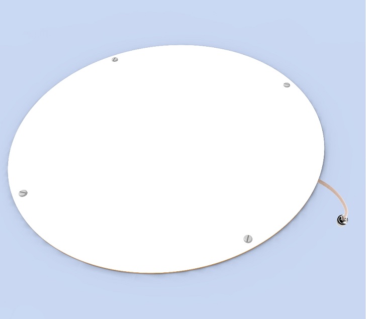
Designed for external Public Safety Radio Frequencies to propagate within buildings, tunnels or public use environments
- Offered with Fire Retardant 6200 Kydex
- Meet the recommended fire safety practices of both the Federal Transit Administration (FTA) and the Federal Rail Administration (FRA) for smoke emission and flammability as tested under ASTM E-662 and ASTM E-162
-
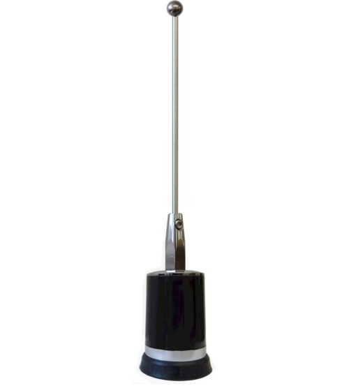
- Provides a dual band frequency range of 700/800 MHz or 800/900 MHz Public Safety bands.
- 2.0 dBd gain achieved over its operating bandwidth
- Manufactured using the best corrosion-resistant materials and finishes available
- Ultrasonically-welded brass insert and leaf spring-loaded contact for long-term reliability
- Standard NMO type mount providing an excellent moisture seal even when the antenna is removed
-
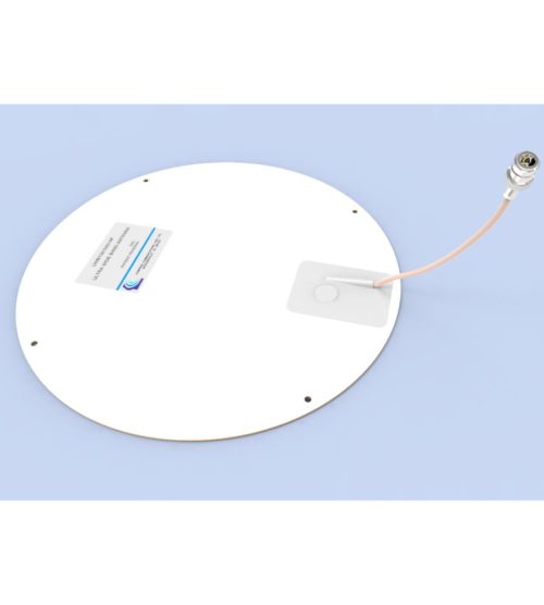
Designed for external Public Safety Radio Frequencies to propagate within buildings, tunnels or public use environments
- Offered with Fire Retardant 6200 Kydex
- Meets the recommended fire safety practices of both the Federal Transit Administration (FTA) and the Federal Rail Administration (FRA) for smoke emission and flammability as tested under ASTM E-662 and ASTM E-162
- The F-3749B Antenna is available in custom colors for orders of 150 or more.
-
Multilayer bonded PCB for high performance and compact design
- Low insertion loss
- Excellent return loss
- Compact dimensions saving space
- 3, 4.8, 6, 7, 10, 15, 20 and 30 dB values
- 200 Watts maximum main line power
- Integrated mounting bracket
-
Multilayer bonded PCB for high performance and compact design
- Low insertion loss
- Excellent return loss
- Compact dimensions saving space
- 3, 4.8, 6, 7, 10, 15, 20 and 30 dB values
- 200 Watts maximum main line power
- Integrated mounting bracket
-
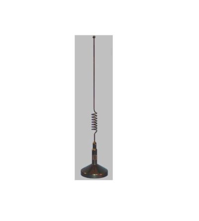
- 3.0 dBd gain achieved by featuring a 5/8-wave above a 1/4 wave closed coil design
- Manufactured using the best corrosion-resistant materials and finishes available
- Magnetic Mounting: Features a powerful magnetic base with a protective Mylar to prevent damage to any mounting service. It is supplied with 12 feet of RG58U coax and your choice of connector. Available with Mini-UHF or TNC connector.
-
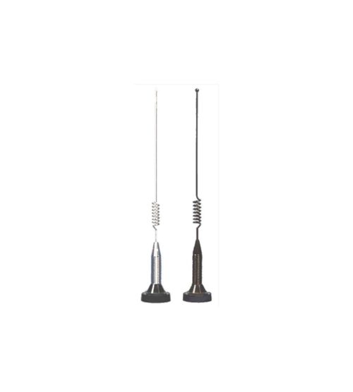
- Addresses First Responder requirements
- 3.0 dBd gain achieved by featuring a 5/8-wave above a 1/4 wave closed coil design
- Manufactured using the best corrosion-resistant materials and finishes available
- Ultrasonically-welded brass insert and leaf spring-loaded contact for long-term reliability
- Standard NMO type mount providing an excellent moisture seal even when the antenna is removed
-
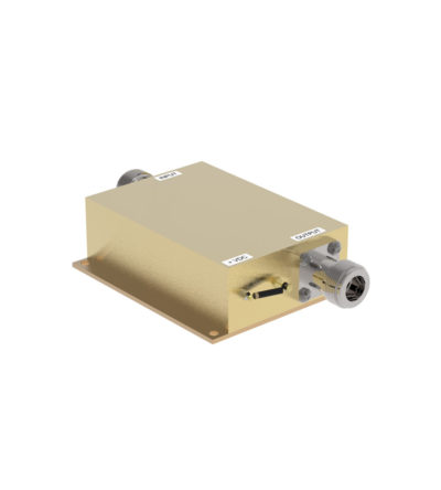
Designed for unconditionally stable performance in professional communications systems
- High gain, low noise
- Maximum performance with minimum noise
- Filtering on DC terminals
- Greater than 70dB attenuation from as low as 5 MHz to several GHz
- High gain, low noise
-
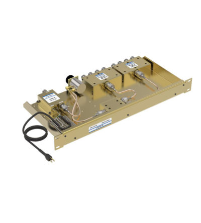
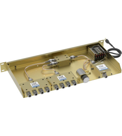
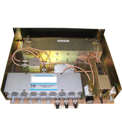
Ideal for combining multiple Rx frequencies onto the same antenna
- Available in 2, 4, 8, 12, 16 and 32
- Simple and cost-effective design
- Standard 19” Rack Mount (RM) or cavity-mounted (CM) versions
- Each unit consists of a power splitter and an RF amplifier.
- Plug-in Power Supply (PS) optional
-
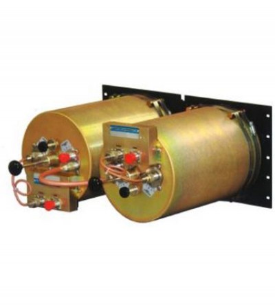
Designed for compact, close frequency installations. Ideal for very closely spaced frequency transmitters
- High isolation: minimizes intermodulation products
- Low loss: maximizes system performance
- Continuous power:
- Physical size and materials used maximizes the performance across the operating band
-
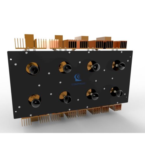
Dielectric resonator technology resulting in higher performance than standard RF cavities in a much smaller package
- Available for the 764-776, 851-869 and 935-941 MHz bands
- Designed for tight channel spacing
- Lowest insertion loss, high isolation for maximum coverage and reduced interference
- Star configuration
- Compact, robust design for rapid installations, increased mobility and ease of maintenance
-
Combines multiple receiver frequencies onto the same antenna
- A low noise amplifier provides gain across the frequency band
- Low noise figure and low intermodulation generation
- Features up to 16 ports (24 and 32 port versions are available)
- -30 dB signal sampler port that can also be used to inject a signal
-
Fully expandable and reconfigurable
- Features X-Pass, plug-and-play technology
- Designed to offer engineers and technicians many options when designing or upgrading a site
-
Dielectric resonator technology resulting in higher performance than standard RF cavities in a much smaller package
- Available for the 764-776, 851-869 and 935-941 MHz bands
- Designed for tight channel spacing
- Lowest insertion loss, high isolation for maximum coverage and reduced interference
- Easy field expandability with X-Pass technology - one channel at a time
- Compact, robust design for rapid installations, increased mobility and ease of maintenance
-
Designed for minimizing interference from adjacent channels and outside systems
- Temperature-compensated to ensure frequency stability
- High attenuation to minimize desense and interference from adjacent systems
- Silver-plated loops and tuning rods
-
Designed for minimizing interference from adjacent channels and outside systems
- Temperature-compensated to ensure frequency stability
- High attenuation to minimize desense and interference from adjacent systems
- Silver-plated loops and tuning rods
-
Designed for minimizing interference from adjacent channels and outside systems
- Temperature-compensated to ensure frequency stability
- High attenuation to minimize desense and interference from adjacent systems
- Silver-plated loops and tuning rods
-
Designed for minimizing interference from adjacent channels and outside systems
- Temperature-compensated to ensure frequency stability
- High attenuation to minimize desense and interference from adjacent systems
- Silver-plated loops and tuning rods
-
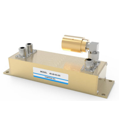
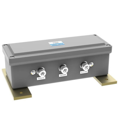
Bi-directional coupler, ideally suited for two-way communications systems
- Low insertion loss
- High isolation between ports
- Excellent VSWR
- Tri-band and other models are available and customizable.
-
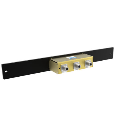
Designed for easy installation, reducing coaxial runs, and in-building applications with multi-band antennas
- Allows multiple bands to share the same transmission lines
- Available in VHF, UHF and 800/900 MHz bands
- Can be Tower-Mounted (TM), Rack-Mounted (RM) or stand alone
-
Designed for easy installation, reducing coaxial runs, and in-building applications with multi-band antennas
- Allows multiple bands to share the same transmission lines
- Available in VHF, UHF and 800/900 MHz bands
- Can be Tower-Mounted (TM), Rack-Mounted (RM) or stand alone
-
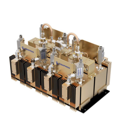
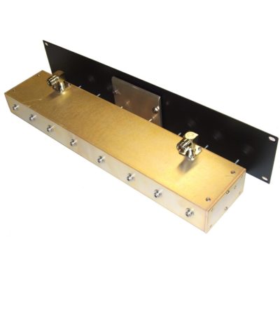
Designed for compact, close frequency installations. Ideal for very closely spaced frequency transmitters
- Ideal for intermodulation panels, providing extra protection with their second harmonic filters, when physical space is at a premium or is constrained, and for providing extra isolation between two very close transmitters
- High isolation: minimizes intermodulation products
- Low loss: maximizes system performance
- Continuous power:
- Physical size and materials used maximizes the performance across the operating band
-
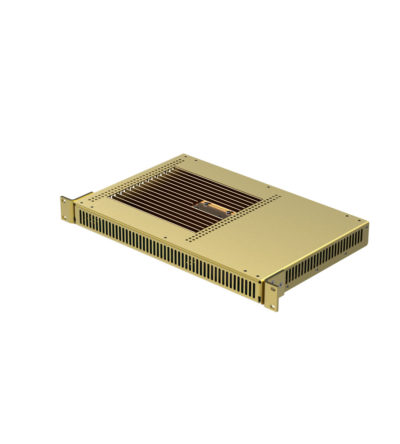
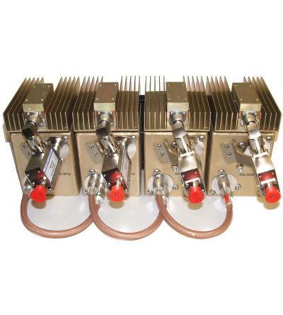
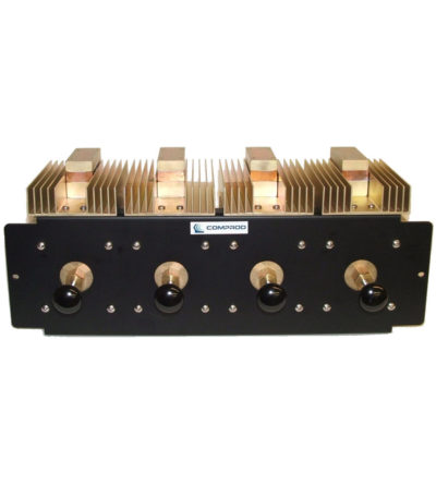
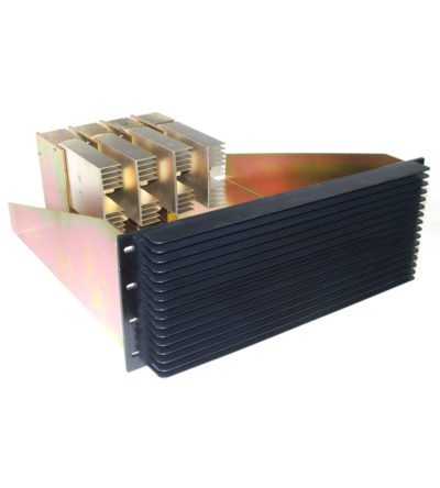
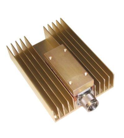
Specifically designed to continually absorb reflected power
- Excellent return loss
- Oversized heat sinks
- Continuous duty power:
- 24/7 operation
- Install-and-forget
-
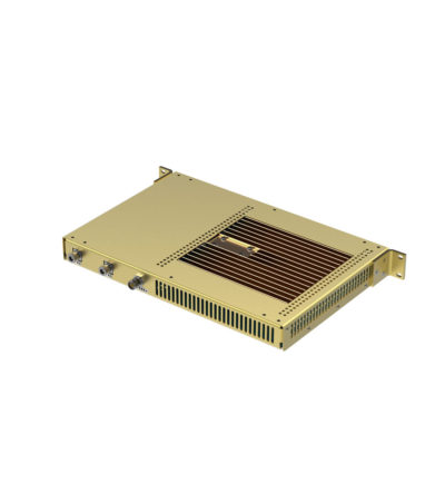
Specifically designed to continually absorb reflected power
- Excellent return loss
- Oversized heat sinks
- Continuous duty power:
- 24/7 operation
- Install-and-forget
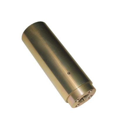
-
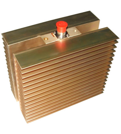
Specifically designed to continually absorb reflected power
- Excellent return loss
- Oversized heat sinks
- Continuous duty power:
- 24/7 operation
- Install-and-forget
-
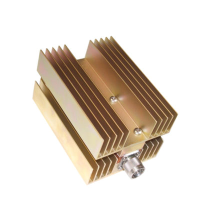
Specifically designed to continually absorb reflected power
- Excellent return loss
- Oversized heat sinks
- Continuous duty power:
- 24/7 operation
- Install-and-forget